DYGD-11 Rail Transit Station BAS Simulation Training Platform
Release time:2024-07-06 04:00viewed:times
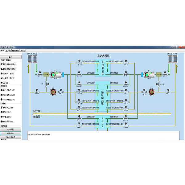
1. Overview
The system is based on the BAS system of the actual subway station of urban r*l transit. It uses computer simulation technology to build a BAS simulation environment of a station, including the station's large system, small system, tunnel ventilation, water system, etc. All operation modes and display modes are consistent with the actual equipment. It can demonstrate the normal working mode, disaster mode and timetable control mode, and can simulate abnormal situations (including various environmental working conditions change settings, equipment f*lures, etc.), providing abnormal situation handling teaching and tr*ning functions.
During teaching, the wind direction and water flow direction of ventilation, *r conditioning and other equipment corresponding to different working modes of the station environmental control system are vividly demonstrated in a dynamic data flow.
During tr*ning, the system is connected according to the station environment and equipment monitoring system architecture, with groups as units. Each group cont*ns 1 station BAS simulation subsystem, 1 environmental control local control virtual simulation cabinet, and 1 virtual IBP disk. Each group can carry out tr*ning independently without affecting each other. During tr*ning, according to the operation process, the direction and water direction of the corresponding ventilation, *r conditioning and other equipment will change dynamically. The
tr*ning results of the system can generate a tr*ning report, and the report results are automatically scored by the system.
Virtual simulation teaching system
Mechanical tr*ning safety education virtual simulation software: This software is developed based on unity3d. The software adopts the form of 3D roaming. The movement can be controlled by the keyboard and the direction of the camera can be controlled by the mouse. There are mechanical safety distance experiments, mechanical safety protection device experiments, and basic assessments of mechanical safety protection design. During the experiment, the 3D roaming screen uses arrows and footprints to prompt movement to the experimental position. The circle around the mechanical object shows the working radius. The experimental process is accompanied by a dialog box reminder of the 3D robot.
A. The content of the mechanical safety distance experiment includes the safety distance experiment to prevent the upper and lower limbs from touching the dangerous area (divided into 2 types of fence heights and opening sizes). After choosing to enter, the GB23821-2009 "Mechanical safety to prevent the upper and lower limbs from touching the dangerous area" requirements pop up in front of the camera. Wrong demonstration: The experimental process is that after the human body enters the working radius of the mechanical object and is injured, the bloody screen and voice reminders are received. Mechanical injury, and return to the original position and conduct the next experiment. The last step is the correct approach.
B. Mechanical safety protection device experiments are divided into safety interlock switches, safety light curt*ns, safety mats, safety laser scanners and other protection device experiments. Optional categories (safety input, safety control, safety output, other), manufacturers, product lists (safety interlock switches, safety light curt*ns, safety mats, safety laser scanners, safety controllers, safety relays, safety fences). The installation location has a blue flashing frame reminder. The experimental process is: select the safety fence and install it, select the safety interlock switch (or select the safety light curt*n, safety mat, safety laser scanner) and install it, select the safety controller and install it to the electrical control box, select the safety relay and install it to the electrical control box, and click the start button on the electrical control box. If you enter the dangerous area, the system will prompt an alarm sound, and the mechanical object will stop working. Select the reset button on the electrical control box to stop.
C. The basic assessment of mechanical safety protection design requires the completion of the installation of the mechanical safety system, the correct installation of safety guardr*ls, safety interlock switches, safety light curt*ns, safety mats, safety laser scanners, safety controllers, safety relays, 24V power supplies, signal lights and emergency stop buttons. The assessment is divided into ten assessment points, some of which have three options, which are freely selected by students. After the final 10 assessment points are selected, submit for confirmation, and the system automatically obt*ns the total score and the score of each assessment point.
D. The software must be on the same platform as a whole and must not be presented as a separate resource.
E. At the same time, the VR installation package of this software is provided to customers to facilitate users to expand it into VR experiments. VR equipment and software installation and debugging do not need to be provided.
Mechanical assembly and bench assembly virtual simulation software: This software is developed based on unity3d, with 6 levels of image quality optional, and has the design and virtual disassembly and assembly of reducers and shaft systems, design and simulation of common mechanical mechanisms , mechanism resource library, and typical mechanical mechanisms (virtual disassembly and assembly of gasoline engines). The software is an overall software and cannot be a separate resource.
A. Reducer design and virtual disassembly and assembly interface can choose worm bevel gear reducer, two-stage expanded cylindrical gear reducer, bevel cylindrical gear reducer, coaxial cylindrical gear reducer, bevel gear reducer, and one-stage cylindrical gear reducer.
Worm bevel gear reducer: After entering the software, the assembly content will be automatically played, and each step in the video will be described in text.
Secondary unfolded cylindrical gear reducer: After entering the software, the content will be played in the form of video. The video content should include: part name (scan the QR code to see the part name), disassembly demonstration (including disassembly, assembly), virtual disassembly (including the whole, low-speed shaft, medium-speed shaft, high-speed shaft, box cover, box seat)
Bevel cylindrical gear reducer, coaxial cylindrical gear reducer, bevel gear reducer, first-level cylindrical gear reducer: click to enter and automatically jump to the edrawings interface. The models are all three-dimensional models . By clicking on the parts to display the part name, you can rotate 360° in all directions, zoom in, zoom out, and translate. At the same time, you can use the move parts function to disassemble and assemble the entire reducer. At the same time, you can select the home button to return to the original state of the reducer. The bevel gear reducer and the first-level cylindrical gear reducer have added the function of inserting cross sections, and the cross sections can be freely dragged to observe the internal structure of the reducer.
B. The design of the shaft system structure and the virtual disassembly and assembly interface can select part recognition, disassembly and assembly demonstration, and actual combat operation.
1. Part recognition: The built-in 3D models and part names of helical gears, end caps without holes, couplings, coupling keys, shafts, gear keys, end caps with holes, sleeves, and deep groove ball bearings are set. Any part can be rotated 360°.
2. Disassembly and assembly demonstration: There are 2 built-in cases. When the mouse is moved to a cert*n part position (except the base and the bearing seat), the part is automatically enlarged and the part name is displayed. There are disassembly and assembly buttons. The software automatically completes the disassembly and assembly of the shaft system structure. The 3D scenes can be rotated 360°, enlarged, reduced, and translated.
3. Actual operation: The 3D parts are neatly placed on the desktop. Students manually select the corresponding parts and move them to the shaft system structure. The parts can be installed only when the placement order and position are correct. There is a restart button to facilitate students to repeat the virtual experiment. When the mouse is moved to a cert*n part position (except the base and the bearing seat), the part is automatically enlarged and the part name is displayed.
C. Common mechanical mechanism design and simulation: Optional hinged four-bar mechanism design and analysis, I\II type crank rocker mechanism design and analysis, offset crank slider mechanism design and analysis, crank swing guide rod mechanism design and analysis, hinged four-bar mechanism trajectory synthesis, eccentric linear roller push rod cam , concentric linear flat push rod cam.
1. Each mechanism should be able to input corresponding parameters, and the software will automatically calculate the parameters, and can perform motion simulation and automatically draw curves.
D. The mechanism resource library can choose 11 types of planar connecting rod mechanisms, 5 types of cam mechanisms, 6 types of gear mechanisms, 8 types of transmission mechanisms, 11 types of clamping mechanisms, 6 types of gear tr*n mechanisms, and 8 types of other mechanisms (mechanical equipment simulation).
E. The virtual disassembly and assembly of gasoline engines can choose crankcase assembly and disassembly demonstration, crankcase virtual assembly, valve system assembly and disassembly demonstration, and valve system virtual assembly.
1. The crankcase assembly and disassembly demonstration and the valve system assembly and disassembly demonstration are both equipped with disassembly buttons, assembly buttons, restart buttons, and decomposition observation buttons. When the mouse moves to a cert*n part position, the part is automatically enlarged and the part name is displayed. The function is automatically completed by the software to complete the disassembly and assembly of the shaft system structure. When the decomposition observation button is used, the crankcase or valve tr*n 3D model automatically displays an exploded view, which can be rotated 360°, zoomed in, zoomed out, and translated.
2. The 3D parts of the crankcase virtual assembly and the valve tr*n virtual assembly are neatly placed on the desktop. Students manually select the corresponding parts and move them to the mechanism. The parts can only be installed when the placement order and position are correct. A restart button is provided to facilitate students to restart the virtual experiment. When the mouse moves to cert*n parts, the part name is automatically displayed.
2. Demonstration teaching function
1. Station large system
-normal working mode (minimum fresh *r, full fresh *r, etc.)
-disaster mode (fire)
-schedule control mode (spring, autumn, summer, winter, etc.)
2. Station small system
-normal working mode (minimum fresh *r, full fresh *r, etc.)
-disaster mode (fire in different equipment rooms)
-schedule control mode (spring, autumn, summer, winter, etc.)
3. Tunnel ventilation system
-normal working mode (morning and evening *r exchange operation, night shutdown, mechanical ventilation, piston ventilation, etc.)
-disaster mode (blockage, fire, etc.)
-schedule control mode
4. Station water system
-*r conditioning season working mode
-non-*r conditioning season working mode
3. Tr*ning function
1. Cognitive tr*ning of station large system working mode
-normal working mode (minimum fresh *r, full fresh *r, etc.)
-disaster mode (fire)
-schedule control mode (spring, autumn, summer, winter, etc.)
2. Cognitive tr*ning of station small system working mode
-normal working mode (minimum fresh *r, full fresh *r, etc.)
-disaster mode (fire in different equipment rooms)
-Schedule control mode
3. Tr*ning on the recognition of tunnel ventilation system working mode
-Normal working mode (morning and evening *r exchange operation, nighttime shutdown, mechanical ventilation, piston ventilation, etc.)
-Disaster mode (blockage, fire, etc.)
-Schedule control mode
4. Tr*ning on the recognition of station water system working mode -Air
-conditioning season working mode
-Non-*r-conditioning season working mode
5. Tr*ning on handling abnormal situations of large station systems
-Remote/local setting of minimum fresh *r (high power) mode tr*ning
-Remote/local setting of minimum fresh *r (low power) mode tr*ning
-Remote/local setting of fresh *r (high power) mode tr*ning
-Remote/local setting of fresh *r (low power) mode tr*ning
-Remote/local setting of ventilation season mode tr*ning
-Remote/local setting of station hall public area fire mode tr*ning
-Remote/local setting of platform public area fire mode tr*ning
-Remote/local setting of station hall commercial area fire mode tr*ning
6. Tr*ning on handling abnormal situations of small station systems
-Remote/local setting of minimum fresh *r (high power) mode tr*ning
-Remote/local setting of minimum fresh *r (low power) mode tr*ning ) mode tr*ning
- remote/local setting of fresh *r (high power) mode tr*ning
- remote/local setting of fresh *r (low power) mode tr*ning
- remote/local setting of ventilation season mode tr*ning
- remote/local setting of inner corridor fire mode tr*ning
- remote/local setting of left/right environmental control room fire mode tr*ning
- remote/local setting of environmental control electric control room fire mode tr*ning
- remote/local setting of m*ntenance room fire mode tr*ning
- remote/local setting of AFC equipment room fire mode tr*ning
- remote/local setting of communication room fire mode tr*ning
- remote/local setting of stationmaster room fire mode tr*ning
- remote/local setting of PSD control room fire mode tr*ning
- remote/local setting of tr*n control room fire mode tr*ning
- remote/local setting of gas cylinder room fire mode tr*ning
7. Tr*ning on abnormal situation handling of tunnel ventilation system
-Remote/local setting of morning and evening ventilation operation mode tr*ning
-Remote/local setting of night shutdown mode tr*ning
-Remote/local setting of mechanical ventilation mode tr*ning -Remote
/local setting of piston ventilation mode tr*ning
-Remote/local setting of upward blocking mode tr*ning -Remote
/local setting of downward blocking mode tr*ning -Remote/local setting of
upward/downward front fire mode tr*ning -Remote
/local setting of upward/downward rear fire mode tr*ning
8. Tr*ning on abnormal situation handling of water system
-Remote/local setting of *r conditioning season mode tr*ning
-Remote/local setting of non-*r conditioning season mode tr*ning
9. Timetable preparation tr*ning
- Spring and autumn working day timetable preparation tr*ning - Spring and autumn
rest day timetable preparation tr*ning - Summer working day timetable preparation tr*ning
- Summer rest day timetable preparation tr*ning
- Winter working day timetable preparation tr*ning - Winter rest day timetable
preparation tr*ning - New Year's Day/Spring Festival/Tomb-Sweeping Day/Dragon Boat Festival/Labor Day/Mid-Autumn Festival/National Day and other holiday timetable preparation tr*ning


 Wechat scan code follow us
