DYGD-10 Rail Transit Station FAS System Simulation Training Platform
Release time:2024-07-06 05:30viewed:times
1. Overview
This system is based on the basic structure of the station fire equipment system, using virtual reality technology and three-dimensional simulation technology to build a realistic station fire alarm system FAS, gas fire extinguishing system and water fire fighting system, providing teaching, tr*ning and assessment functions such as d*ly use of station fire equipment and fire condition handling.
The system consists of three parts: teaching, tr*ning and examination system.
The teaching system builds three-dimensional virtual station fire equipment and fire equipment scenes. Taking the EST3 host as an example, it introduces the structure, equipment composition, d*ly operation and use of equipment, fire condition handling and other teaching functions of station fire equipment through plane and three-dimensional methods combined with multimedia display. The
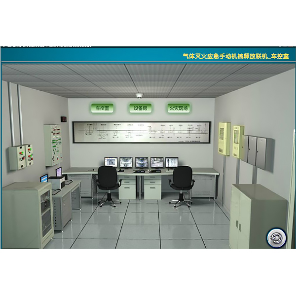
tr*ning system is connected according to the working structure of the station fire system in the three-dimensional virtual fire scene, equipment room, car control room and other scenes related to fire facilities. It is based on groups. Each group cont*ns car control room, equipment room and fire scene, and can carry out tr*ning independently without affecting each other.
The examination system includes examination module and examination management module.
Among them, the examination module of the examination system is carried out on virtual fire equipment. The examination questions should include objective theoretical questions and operation questions, and can be automatically scored.
The examination management module can manage the question bank (operational questions, objective theory questions), paper bank management, candidate management, paper distribution, candidate scores in the form of individuals and classes, and export the corresponding results to EXCE-reports. Teachers should be able to edit and modify the standard answers to operational questions and theoretical questions.
Virtual simulation teaching system
mechanical tr*ning safety education virtual simulation software: This software is developed based on unity3d. The software adopts the form of three-dimensional roaming. The movement can be controlled by the keyboard and the direction of the lens can be controlled by the mouse. There are mechanical safety distance experiments, mechanical safety protection device experiments, and basic assessments of mechanical safety protection design. When the experiment is in progress, the three-dimensional roaming screen uses arrows and footprints to prompt movement to the experimental position. The circle around the mechanical object shows the working radius. The experimental process is accompanied by a dialog box reminder of the three-dimensional robot.
A. The content of the mechanical safety distance experiment includes the safety distance experiment to prevent the upper and lower limbs from touching the dangerous area (with two types of fence height and opening size). After entering, the GB23821-2009 "Safety distance to prevent the upper and lower limbs from touching the dangerous area" requirement pops up in front of the camera. Wrong demonstration: the experiment process is that after the human body enters the working radius of the mechanical object and is injured, the bloody picture and voice reminder receive mechanical injury, and return to the original position and conduct the next experiment. The last step is the correct approach.
B. The mechanical safety protection device experiment is divided into safety interlock switch, safety light curt*n, safety mat, safety laser scanner and other protection device experiments. The optional categories (safety input, safety control, safety output, other), manufacturer, product list (safety interlock switch, safety light curt*n, safety mat, safety laser scanner, safety controller, safety relay, safety fence). There is a blue flashing frame reminder at the installation location. The experimental process: select the safety fence and install it, select the safety interlock switch (or select the safety light curt*n, safety mat, safety laser scanner) and install it, select the safety controller and install it to the electrical control box, select the safety relay and install it to the electrical control box, and click the start button on the electrical control box. If you enter the dangerous area, the system will prompt an alarm sound, and the mechanical object will stop working. You can stop by selecting the reset button on the electrical control box.
C. The basic assessment of mechanical safety protection design requires the installation of the mechanical safety system to be completed, and the safety guardr*l, safety interlock switch, safety light curt*n, safety mat, safety laser scanner, safety controller, safety relay, 24V power supply, signal light and emergency stop button to be correctly installed. The assessment is divided into ten assessment points. Some assessment points have 3 options, which are freely selected by students. After the final 10 assessment points are selected, submit for confirmation, and the system automatically obt*ns the total score and the score of each assessment point.
D. The software must be the same platform as a whole and shall not be displayed as a separate resource.
E. At the same time, the VR installation package of this software is provided to customers to facilitate users to expand it into VR experiments. VR equipment and software installation and debugging do not need to be provided.
Mechanical assembly and bench assembly virtual simulation software: This software is developed based on unity3d, with 6 levels of image quality optional, and has the design and virtual disassembly and assembly of reducers and shafting structures, design and simulation of common mechanical mechanisms , mechanism resource library, typical mechanical mechanisms (virtual disassembly and assembly of gasoline engines). The software is an overall software and cannot be a separate resource.
A. Reducer design and virtual disassembly and assembly interface can choose worm bevel gear reducer, two-stage expanded cylindrical gear reducer, bevel cylindrical gear reducer, coaxial cylindrical gear reducer, bevel gear reducer, and one-stage cylindrical gear reducer.
Worm bevel gear reducer: After entering the software, the assembly content will be automatically played, and each step in the video will be described in text.
Secondary unfolded cylindrical gear reducer: After entering the software, the content will be played in the form of video. The video content should include: part name (scan the QR code to see the part name), disassembly demonstration (including disassembly, assembly), virtual disassembly (including the whole, low-speed shaft, medium-speed shaft, high-speed shaft, box cover, box seat)
Bevel cylindrical gear reducer, coaxial cylindrical gear reducer, bevel gear reducer, first-level cylindrical gear reducer: click to enter and automatically jump to the edrawings interface. The models are all three-dimensional models . By clicking on the parts to display the part name, you can rotate 360° in all directions, zoom in, zoom out, and translate. At the same time, you can use the move parts function to disassemble and assemble the entire reducer. At the same time, you can select the home button to return to the original state of the reducer. The bevel gear reducer and the first-level cylindrical gear reducer have added the function of inserting cross sections, and the cross sections can be freely dragged to observe the internal structure of the reducer.
B. The design of the shaft system structure and the virtual disassembly and assembly interface can select part recognition, disassembly and assembly demonstration, and actual combat operation.
1. Part recognition: The built-in 3D models and part names of helical gears, end caps without holes, couplings, coupling keys, shafts, gear keys, end caps with holes, sleeves, and deep groove ball bearings. Any part can be rotated 360°.
2. Disassembly and assembly demonstration: There are 2 built-in cases. When you move the mouse to a cert*n part position (except the base and bearing seat), the part will automatically enlarge and display the part name. There are disassembly and assembly buttons. The software automatically completes the disassembly and assembly of the shaft system structure. The 3D scenes can be rotated 360°, enlarged, reduced, and translated.
3. Actual operation: The three-dimensional parts are neatly placed on the desktop. Students manually select the corresponding parts and move them to the shaft structure. The parts can only be installed when the placement order and position are correct. There is a restart button to facilitate students to repeat the virtual experiment. When the mouse moves to a cert*n part position (except the base and the bearing seat), the part is automatically enlarged and the part name is displayed.
C. Common mechanical mechanism design and simulation optional hinge four-bar mechanism design and analysis, I\II type crank rocker mechanism design and analysis, offset crank slider mechanism design and analysis, crank swing guide rod mechanism design and analysis, hinge four-bar mechanism trajectory synthesis, eccentric linear roller push rod cam , concentric linear flat bottom push rod cam .
1. Each mechanism should be able to input the corresponding parameters, and the software will automatically calculate the parameters, and can perform motion simulation and automatically draw curves.
D. The mechanism resource library can choose 11 types of planar connecting rod mechanisms, 5 types of cam mechanisms, 6 types of gear mechanisms, 8 types of transmission mechanisms, 11 types of tightening mechanisms, 6 types of gear tr*n mechanisms, and 8 types of other mechanisms (mechanical equipment simulation).
E. Virtual disassembly and assembly of gasoline engines can choose crankcase assembly and disassembly demonstration, crankcase virtual assembly, valve system assembly and disassembly demonstration, and valve system virtual assembly.
1. The crankcase assembly and disassembly demonstration and the valve system assembly and disassembly demonstration are equipped with disassembly buttons, assembly buttons, restart buttons, and decomposition observation buttons. When the mouse moves to a cert*n part position, the part is automatically enlarged and the part name is displayed. The function is automatically completed by the software to disassemble and assemble the shaft system structure. When the decomposition observation button is used, the three-dimensional model of the crankcase or valve system automatically displays an exploded view, which can be rotated 360° in all directions, enlarged, reduced, and translated.
2. The three-dimensional parts of the crankcase virtual assembly and the valve system virtual assembly are neatly placed on the desktop. Students manually select the corresponding parts and move them to the mechanism. The parts can only be installed when the placement order is correct and the position is correct. There is a restart button to facilitate students to re-conduct virtual experiments. When you move the mouse to cert*n parts, the names of the parts will be automatically displayed.
2. Teaching functions
1. FAS system teaching functions
1) Understanding of the structure of the FAS system
2) Understanding of the components and functions of the FAS (three-dimensional virtual station scene display)
3) Understanding of the FAS alarm host control panel
4) Understanding of the status of the FAS alarm host display
5) Understanding of the FAS system's alarm graphical monitoring workstation CRT
6) Understanding of automatic alarms
7) Manual alarm operations
8) Understanding of the fire alarm handling process
9) Understanding of d*ly inspections of the
station FAS system 10) Understanding of the periodic m*ntenance of the station FAS system
2. Gas fire extinguishing system teaching functions
1) Understanding of the structure of the gas fire extinguishing system
2) Understanding of the components and functions of the gas fire extinguishing system (three-dimensional virtual station scene display)
3) Understanding of the gas fire extinguishing alarm host control panel
4) Understanding of the status of the gas fire extinguishing alarm host display
5) Understanding of the gas extinguishing Fire control panel control panel cognition
6) Gas fire extinguishing control panel operation cognition
7) Gas fire extinguishing system detection alarm
8) Gas fire extinguishing system automatic fire extinguishing
9) Gas alarm fire extinguishing disposal process cognition
10) Gas fire extinguishing control panel manual release fire extinguishing
11) Emergency manual mechanical release fire extinguishing
12) Disposal in case of misoperation or fire extinguishing with fire extinguisher
13) D*ly inspection cognition of station gas fire extinguishing system
14) Periodic m*ntenance cognition of station gas fire extinguishing system
3. Water fire fighting teaching function
1) Fire hydrant system structure, composition equipment and function (three-dimensional virtual station scene display)
2) Water sprinkler system structure, composition equipment (three-dimensional virtual station scene display) and function
3) Use of fire extinguisher
4) Use of fire hydrant
5) Water sprinkler
6) D*ly inspection cognition of station water fire fighting system
7) Periodic m*ntenance
cognition 2. Tr*ning functions
1. Water sprinkler automatic mode tr*ning
2. Water sprinkler manual mode tr*ning
3. Fire hydrant automatic mode tr*ning
4. Fire hydrant manual mode tr*ning
5. Gas fire extinguishing manual mode tr*ning
6. Gas fire extinguishing automatic mode tr*ning
7. Gas fire extinguishing misoperation treatment tr*ning
3. Examination and management functions
1. Examination functions:
- Student login
- Candidate answering questions
- Candidate submitting papers
- Automatic scoring
2. Examination organization and management functions:
- Question bank management (theoretical questions and operational questions)
- Paper bank management
- Paper distribution
- Candidate management
-Student score statistics and score EXCE-Report export
3. Operation questions include:
-Fire hydrant fire extinguishing operation
-Fire extinguisher fire extinguishing operation
-Gas fire extinguishing emergency operation
-Manual start gas fire extinguishing system operation
-Water sprinkler pump emergency pump operation
-Fire hydrant pump emergency *r pump operation
-Fire hydrant pump emergency pump stop operation


 Wechat scan code follow us
