DYSYX-ZDJ Automatic control/computer control principle experimental device
Release time:2024-07-03 13:00viewed:times
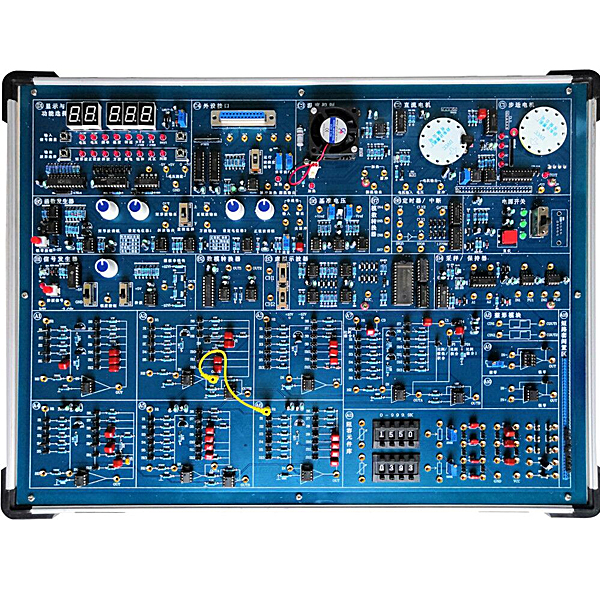
1. System composition
1. Power supply: input single-phase three-wire ~ 220V ± 10% 50Hz. Output DC ± 5V / 2A, ± 12V / 0.5A power supply, both with reverse connection and short circuit protection functions.
2. Core system: Adopt 8088 microprocessor, convenient for computer control technology software programming; RS232 bus interface communicates with the host computer (USB interface communication is possible), cont*ns the host computer total reset and manual total reset circuit, cont*ns automatic zero lock and manual zero lock function.
3. Function generator: The experimental machine comes with signal measurement and signal display module
It can measure signal voltage (-5V ~ + 5V), frequency, temperature, speed and other parameters.
4. Step signal generator: manual step generation (0/+5v, -5v/+5v), amplitude control (potentiometer), nonlinear output group.
5. Function signal generator: It can output sine wave, ramp wave, square wave, rectangular wave, relay characteristic, saturation characteristic, dead zone characteristic and gap characteristic. It has switch switching and a digital tube to display waveform related information. The frequency range of sine wave signal is 0.1HZ~2HZ and 0.8HZ~50HZ, with a resolution of 0.1HZ and 1HZ. The frequency range of other waveforms is 0.1HZ~250HZ, with a resolution of 0.1HZ. The amplitude range of waveform signal is -6V~+6V, the amplitude resolution is 0.1V, and the distortion is not more than 0.5%. The impedance is not more than 50Ω.
6. Operation simulation unit: It provides 8 OP07 basic operational amplifier simulation units (for experiments). The input circuit of each unit has 6 groups of 0.5% precision resistors or 5% precision capacitors, and the feedback circuit has 7 groups of 0.5% precision resistors or 5% precision capacitors, and 1 operational amplifier. There are also extended operational amplifier simulation units, one of which is an adjustable zero amplifier, which can form proportional links, inertial links, integral links, proportional differential links, PID links and typical second-order and third-order systems; the second is a correction network library, which can form various correction links; the third is 2 groups of shaping modules.
7. Provides a library of resistors and capacitors: 250K, 500K potentiometers, 2 groups of 0-999.9K direct-reading variable resistors, and multiple groups of capacitors.
8. 1 group of D/A output: voltage 0~5V or -5V~+5V.
9. 4-way A/D input: 2 channels are 0~+5v voltage input, and 2 channels are -5v~+5v voltage input.
10. 2 groups of sample-and-hold and monostable unit circuits.
11. Provides precise reference voltages +Vref and -Vref.
12. Timing and interrupt units: 2 groups of timing counters and 2 interrupt sources.
9. Provide virtual oscilloscope:
1) 2 channels analog signal input: can measure phase plane display, frequency dom*n logarithmic amplitude-frequency, phase-frequency curve, amplitude-phase curve, etc.
2) Oscilloscope time dom*n display mode: oscilloscope phase plane display (XY) mode; oscilloscope frequency characteristic display mode includes logarithmic amplitude-frequency characteristic display, logarithmic phase-frequency characteristic display (Bode diagram), amplitude-phase characteristic display mode (Nyquist diagram), time dom*n analysis (radian) display mode.
3) Oscilloscope computer control display mode.
10. Peripheral control objects
1) Stepper motor (35BY48) speed and angle control.
2) DC motor (BY25) pulse speed measurement output and voltage speed measurement output.
3) Temperature module adjustable pulse width input control and voltage input control heating, thermistor temperature measurement (0℃~76.5℃).
11. Support secondary development: In addition to the analog operation unit and function generator, the 8253 timer, 8259 interrupt controller, analog-to-digital converter, and digital-to-analog converter address of this experimental machine are also open to users.
12. Support automatic detection of the entire system: It can help the experimental administrator to find and solve problems in time to ensure the normal development of students' experimental courses.
13. Chassis: Sturdy aluminum alloy frame, thick ABS plastic corners, reference size 480×360×120mm.
14. Virtual simulation software for mechanical tr*ning safety education: This software is developed based on unity3d. The software adopts the form of three-dimensional roaming. The movement can be controlled by the keyboard and the direction of the lens can be controlled by the mouse. There are mechanical safety distance experiments, mechanical safety protection device experiments, and basic assessments of mechanical safety protection design. When the experiment is in progress, the three-dimensional roaming screen uses arrows and footprints to prompt moving to the experimental position. The circle around the mechanical object shows the working radius. The experimental process is accompanied by a dialog box reminder of the three-dimensional robot.
A. The content of the mechanical safety distance experiment includes the safety distance experiment to prevent the upper and lower limbs from touching the dangerous area (with two types of fence heights and opening sizes). After entering, the GB23821-2009 "Safety distance to prevent the upper and lower limbs from touching the dangerous area for mechanical safety" requirements pops up in front of the camera. Wrong demonstration: The experimental process is that after the human body enters the working radius of the mechanical object and is injured, the bloody picture and voice reminder receive mechanical injury, and return to the original position and conduct the next experiment. The last step is the correct approach.
B. The mechanical safety protection device experiment is divided into safety interlock switch, safety light curt*n, safety mat, safety laser scanner and other protection device experiments. The optional categories (safety input, safety control, safety output, other), manufacturer, product list (safety interlock switch, safety light curt*n, safety mat, safety laser scanner, safety controller, safety relay, safety fence). There is a blue flashing frame reminder at the installation location. The experimental process: select the safety fence and install it, select the safety interlock switch (or select the safety light curt*n, safety mat, safety laser scanner) and install it, select the safety controller and install it to the electrical control box, select the safety relay and install it to the electrical control box, and click the start button on the electrical control box. If entering a dangerous area, the system will sound an alarm and the mechanical object will stop working. You can stop it by pressing the reset button on the electrical control box.
C. The basic assessment of mechanical safety protection design requires the completion of the installation of the mechanical safety system, the correct installation of safety guardr*ls, safety interlock switches, safety light curt*ns, safety mats, safety laser scanners, safety controllers, safety relays, 24V power supplies, signal lights and emergency stop buttons. The assessment is divided into ten assessment points. Some assessment points have 3 options, which students can choose freely. After the final 10 assessment points are selected, submit for confirmation, and the system will automatically derive the total score and the score of each assessment point.
D. The software must be on the same platform as a whole and must not be displayed as a separate resource.
E. At the same time, the VR installation package of this software is provided to customers to facilitate users to expand into VR experiments. VR equipment and software installation and debugging do not need to be provided.
2. Experimental projects
Automatic control experiment
1. Time dom*n analysis of linear systems: 1) Simulation study of typical links; 2) Transient response and stability of second-order systems; 3) Transient response and stability of third-order systems.
2. Frequency dom*n analysis of linear control systems (Bode diagram, Nyquist diagram): 1) Frequency characteristic curve of inertial link; 2) Frequency characteristic curve of second-order closed-loop system; 3) Frequency characteristic curve of second-order open-loop system; 4) Time dom*n analysis of frequency characteristics.
3. Phase plane analysis of nonlinear systems: 1) Typical nonlinear links; 2) Second-order nonlinear control systems: 3) Third-order nonlinear control systems.
4. Correction and state feedback of linear systems: 1) Correction of linear systems; ① Frequency dom*n method series lead correction; ② Time dom*n method series proportional differential correction; ③ Time dom*n method proportional feedback correction; ④ Time dom*n method differential feedback correction; 2) State feedback and pole configuration of linear systems.
5. Sampling control system analysis
6. Simulated DC motor closed-loop speed regulation experiment
7. Simulated temperature closed-loop control experiment
Computer control technology experiment
1. Digital/analog conversion experiment
2. Analog/digital conversion experiment
3. Sampling and holding: 1) Sampling experiment; 2) Sampling/holding device experiment; 3) Sampling/holding control system analysis example.
4. Smoothing and digital filtering experiment: 1) Differentiation and smoothing; 2) Digital filtering.
5. Digital PID control experiment: 1) Standard PID control algorithm, 2) Integral separation PID control algorithm: 3) Nonlinear PID control algorithm; 4) Integral separation-bang bang compound PID control algorithm
6. Minimum beat control system: 1) Minimum beat ripple system; 2) Minimum beat ripple-free design; 3) Minimum beat control system design example.
7. Dalin algorithm: 1) Dalin algorithm with obvious ringing phenomenon and ringing elimination; 2) Dalin algorithm with weak ringing phenomenon and ringing elimination; 3) Dalin algorithm without ringing phenomenon.
8. Multivariable decoupling control: 1) Multivariable decoupling control design; 2) Multivariable decoupling control design.
9. Secondary development of microcomputer control
Control system experiment
1. DC motor closed-loop speed regulation experiment
2. Temperature closed-loop control experiment
3. Stepper motor speed regulation experiment
4. Analog/digital hybrid temperature closed-loop control experiment


 Wechat scan code follow us
