Shanghai Daiyu Education Equipment Manufacturing Co., Ltd.
Language:


| model | WWGI50 | ||
| Fan input parameters | |||
| Rated input power | 10kW | ||
| Rated input voltage | 380Vdc | ||
| Input voltage range | 0~600Vdc | ||
| Cut-in voltage | 60Vdc (factory value, 60Vdc~360Vdc can be set) | ||
| Rated input current | 10Adc | ||
| manual brake | After long pressing the button for 5 seconds, it will be completely unloaded and needs to be restored manually (press and hold ag*n for 5 seconds to restore) | ||
| When the *r switch is closed, the three-phase AC short circuit | |||
| Overvoltage braking | When 360Vdc (factory value, 60Vdc~600Vdc can be set) reaches the unloading voltage, it starts PWM step-by-step unloading. When the voltage increases ag*n, it is completely unloaded at 20Vdc. | ||
| Overwind speed braking (optional) | 14m/s (0-30m/s can be set), completely unloaded when reaching the system set wind speed, and automatically restored after 10 minutes | ||
| Over-speed braking (optional) | 500 rpm (factory value, 0~1000 rpm can be set), it will be completely unloaded when it reaches the system set speed, and will automatically recover after 10 minutes; | ||
| AC output parameters | |||
| Number of grid phases | Three phases | ||
| Rated output power | 10KW | ||
| Rated grid voltage | 380Vac | ||
| Grid voltage range | 310~450Vac | ||
| Rated grid frequency | 50Hz | ||
| Operating frequency range | 47~55Hz | ||
| Rated grid output current | 8A | ||
| Maximum output current | 9A | ||
| efficiency | |||
| Maximum conversion efficiency | ≥96% | ||
| Protective function | |||
| DC input side overvoltage protection | have | ||
| AC output side overvoltage/undervoltage protection | have | ||
| AC output overfrequency/underfrequency | have | ||
| DC reverse polarity protection | have | ||
| DC input overload protection | have | ||
| AC short circuit protection | have | ||
| surge protection | have | ||
| Anti-islanding protection | have | ||
| Over temperature protection | have | ||
| Rectification method | Uncontrolled rectification | ||
| Display method | LCD | ||
| Display content | Fan voltage, fan current, fan power; grid voltage, grid-connected current, grid-connected power, accumulated power generation, fault code, etc. | ||
| Monitor mode (optional) | RS232/RS485/GPRS | ||
| Monitor content | Fan voltage, fan current, fan power; grid voltage, grid-connected current, grid-connected power, accumulated power generation, fault code, etc. | ||
| Isolation method | No transformer | ||
| Lightning protection | have | ||
| ambient temperature | -20℃~+60℃ | ||
| humidity | 4%~100%, with condensation | ||
| noise | ≤65dB | ||
| cooling method | *r cooling | ||
| Installation method | Wall-mounted | ||
| Enclosure rating | IP65 | ||
| Product size (width × height × depth) | 406×540×219mm | ||
| Product Weight | 29kg | ||
| Unloading box size (width × height × depth) | 390×730×190mm | ||
| Net weight of unloading box | 19kg | ||
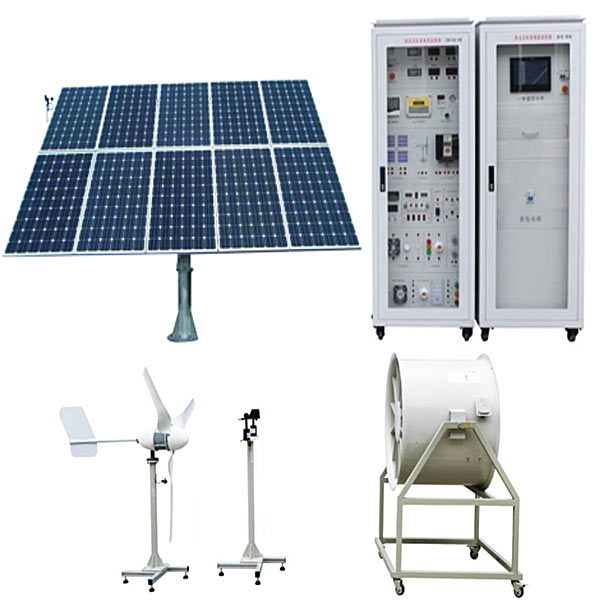
| model | SHF-10000 |
| rated power | 10.0W |
| Maximum power | 12kW |
| Rated voltage | 120V/220V/380V |
| Start wind speed | 2.5m/s |
| Rated wind speed | 18m/s |
| maximum wind speed | 45m/s |
| Net weight of fan | 350kg |
| Wind wheel diameter | 2m |
| Tower height | 9m |
| Blade height | 3.6m |
| Number of leaves | 4 slices |
| Blade material | Aluminum alloy |
| dynamo | Three-phase AC permanent magnet synchronous generator/permanent magnet levitation generator |
| Tower type | independent tower |
| Protect | Fan self-rotation protection/electromagnetic braking |
| Operating temperature | -40℃-80℃ |
| model | 10KW tower | |
| tower pole | Independent tower (m) | 12 |
| foundation | Center foundation (m) | 1.2*1.2*1.5 |
| Photovolt*c side input | |
| Maximum input power (kW) | 10 |
| MPPT voltage range (V) | 120-850 |
| Input voltage range (V) | 100-1000 |
| Number of MPPTs | 2 |
| AC output-grid connection status | |
| Maximum output power (kW) | 12 |
| Output voltage range (V) | 3N-400, 324-436, 437-460 (<10 minutes) |
| Rated voltage & frequency (V/Hz) | 380±2%,50±2% (grid matching) |
| Output power(kW) | Rated power 10.0, instantaneous power 12.0 |
| Maximum output current (A) | 22 Three-phase balance |
| Total current waveform distortion rate | <3% |
| Island protection | system build-in |
| power factor | (-0.95, +0.95) |
| serial number | project | Parameters and requirements | |
| 1 | battery information | Battery specifications and models | 48V50Ah |
| 2 | Nominal capacity | 50Ah | |
| 3 | Battery module nominal voltage | 50V | |
| 4 | Single cell nominal voltage | 3.2V | |
| 5 | Single combination of battery modules | 16 strings | |
| 6 | Battery module weight (kg) | ≈65 | |
| 7 | Charging parameters | Maximum charging current (A) | 50 |
| 8 | Battery module charging voltage range (V) | 45~54 | |
| 9 | Battery module charging cut-off voltage | 52.5V~54 | |
| 10 | Standard charging method | 20A equal charge to 52.5V-54V float charge | |
| 11 | Battery module charging time | 5~6h (20A) | |
| 12 | Discharge parameters | Maximum discharge current (A) | 100 |
| 13 | Battery module discharge voltage range (V) | 54~45 | |
| 14 | Battery module discharge cut-off voltage | 45V | |
| 15 | Single cell discharge cut-off voltage | 2.82V | |
| 16 | Short circuit protection parameters | Short circuit protection current (A) | 250A |
| 17 | Short circuit protection delay time (us) | 500 | |
| 18 | Short circuit protection recovery method | Connect the charger | |
| 19 | Self-consumption and sleep parameters | Internal circuit consumption during operation (mA) | ≤70 |
| 20 | Internal consumption during sleep (uA) | ≤2000 | |
| twenty one | shell | shell material | Galvanized steel plate, surface sprayed |
| twenty two |
Battery pack dimensions |
Height (mm) | 89 |
| twenty three | Width(mm) | 410 (total width with mounting ears), 440 (cabinet) | |
| twenty four | Length(mm) | 410 (cabinet depth) | |
| 25 | equipment weight | 24KG (battery) | |
| 26 | work and storage | Operating temperature | Charging: 0~45℃; Discharging: -20~60℃ |
| 27 | storage temperature | -10~35℃ | |
| 28 | Relative humidity | 5%~85% | |
| 29 | Management System (BMS) | Management system functions | Cell voltage management, total voltage management, charge and discharge temperature management, charge and discharge current management, battery balance management, overcharge protection, over-discharge protection, over-temperature protection, over-current protection, short-circuit protection, etc. |
| Function | S#stem BMS | RackBMS | Tra# BMS | |
| Detection | Rack voltage/current | - | ○ | - |
| Cell voltage/temperature | - | - | ○ | |
| Module voltage | - | - | ○ | |
| calculate | capacity estimate | ○ | ○ | - |
| health status estimate | ○ | ○ | - | |
| Power prediction | ○ | ○ | - | |
| Resistance calculation | ○ | ○ | - | |
| control | fan control | - | - | ○ |
| switch control | - | ○ | - | |
| voltage balance | - | ○ | ○ | |
| communication | CAN | ○ | ○ | ○ |
| RS-485 or Modbus-TCP/IP | ○ | - | - | |
| Product number | PWS1-50K | ||
| Battery side parameters | |||
| DC voltage range | 500V~850V | ||
| DC maximum current | 110A | ||
| Maximum DC power | 55kw | ||
| AC grid connection parameters | |||
| Rated output power | 50kW | ||
| Rated grid voltage | 400V | ||
| Grid voltage range | ±15% | ||
| Grid frequency range | 50Hz/60Hz | ||
| Grid frequency range | ±2.5Hz | ||
| AC rated current | 72A | ||
| OutputTHDi | ≤3% | ||
| Grid power factor | -1~+1 | ||
| Exchange off-grid parameters | |||
| AC off-grid voltage | 400V | ||
| AC voltage adjustable range | ±10% | ||
| AC off-grid frequency | 50Hz/60Hz | ||
| Off-grid output THDu | ≤2% (linear load) | ||
| System parameters | |||
| The highest efficiency of the whole machine | 97.3% | ||
| Wiring | Three-phase three-wire | ||
| Isolation method | Power frequency isolation | ||
| cooling method | Forced *r cooling | ||
| noise | 70dB | ||
| temperature range | -20℃~50℃ | ||
| Protection level | IP20 | ||
| altitude | 3000M | ||
| Humidity range | 0~95% | ||
| size | 800*2160*800 | ||
| weight | 465kg | ||
| communication method | |||
| show | touchscreen | ||
| Host computer communication method | ModBusTCP/IP | ||
| Communication Interface | Network port, RS485, CAN | ||
| Ambient temperature T | Inverter operating conditions |
| T≤50℃ | The inverter can operate under 1.1 times overload condition for a long time |
| 50℃<T≤55℃ | The inverter operates with derating at a slope of 10kW/°C. |
| 55℃<T≤65℃ | The inverter operates at a derating rate of 50kW/°C. |
| T>65℃ |
The inverter enters protection mode; when the ambient temperature drops below 55°C, the inverter will automatically restart operation. |
| Det*led specifications | Product number | ACL007A |
| Charging equipment | Installation method | Vertical |
| Equipment size | 724*215*1500 | |
| Wiring method | In and out | |
| Input voltage | AC220V±15% | |
| input frequency | 50±3Hz | |
| The output voltage | AC220V±15% | |
| Maximum output current | 32A | |
| Cable length | 4m | |
| Measuring accuracy | Level 1 | |
| Electrical indicators | Current limiting protection value | ≥110% |
| Voltage stabilization accuracy | / | |
| Steady flow accuracy | / | |
| Ripple coefficient | / | |
| efficiency | / | |
| power factor | / | |
| Harmonic content THD | / | |
| feature design | HMI | 4.3-inch LCD display touch screen |
| Charging mode | Automatic full charge/fixed battery/fixed amount/fixed time | |
| charging method | Swipe card to charge, scan QR code to charge | |
| payment method | Pay by card or scan QR code to pay | |
| Networking method | Ethernet 3/4G | |
| Safe design | Safety standards | GB/T20234, GB/T18487, GB/T27930, NB/T33008, NB/T33002 |
| security function | Overvoltage protection, undervoltage protection, overload protection, short circuit protection, grounding protection, overtemperature protection, low temperature protection, lightning protection, emergency stop protection, leakage protection | |
| Environmental indicators | Operating temperature | -25℃~+55℃ |
| Working humidity | 5%~95% frost-free | |
| Working altitude | ≤2000m | |
| Protection level | IP54 | |
| cooling method | Naturally cold | |
| Noise control | ≤60dB | |
| MTBF | 100,000 hours |
| level | content | Remark |
| intermediate | PLC working principle control, program execution process, motor start and stop control, motor forward and reverse control, motor cycle forward and reverse control, three-speed motor control | |
| advanced | Star/angle starting control, motor forward and reverse energy consumption braking control, lantern cycle control, digital tube lighting control, large and small ball conveyor control, simple manipulator control | |
| technician | Control of electroplating production lines, control of automatic traffic lights, control of belt conveyor lines, control of industrial washing machines, control of constant pressure water supply systems, control of trolleys, control of parking spaces, PU operation of inverters, and EXT of inverters operation, combined operation of the inverter | |
| comprehensive | Operation of handheld programmer, X62W universal milling and turning, Z3050 radial drilling machine, CA6140 lathe |
 Wechat scan code follow us

24-hour hotline+86 18916464525

Phone18916464525
ADD:Factory 414, District A, No. 6, Chongnan Road, Songjiang Science and Technology Park, Shanghai ICP: Sitemap