DYSYX-XH signal and system experimental device
Release time:2024-07-03 08:30viewed:times
1. System Features
Our company specially designed it for the "Signal and System" course. It is cost-effective and practical. It is suitable for teaching experiments in various colleges and universities. The experimental box has the following characteristics:
1. Closely follow the teaching syllabus, concise content, and highlight the key points: Most chapters of the "Signal and System" course are provided with experimental projects, which makes the experimental content educational and universal, and also enables students to master the principle knowledge more thoroughly through the experimental links.
2. Circuit modular design: The experimental units are divided into modules, and the experimental names correspond to the module names. The circuits in the modules are drawn in the corresponding positions, so that the experimenters can see it at a glance.
3. Compact structure, stable and reliable performance; strong expansibility, and can design experimental circuits by themselves.
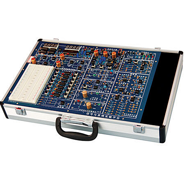
2. System composition
The experimental box is composed of functional modules and experimental modules.
Functional modules:
1. Power input module: Provides power output of +5V/1.0A, -5V/0.5A, +12V/0.5A, -12V/0.5A.
2. Function generator module: provides five waveform signals: sine wave, triangle wave, square wave, rectangular wave, and sweep signal.
The frequency range of the signal: 8Hz-100KHz, divided into four frequency bands.
The frequency, amplitude, duty cycle and sweep speed of the signal are adjustable.
3. Frequency meter: four-digit display, measurement range 1Hz-300KHz, automatic range switching.
4. Millivolt meter: three-and-a-half-digit display, measurement range 0-20V, frequency range 0-100KHz.
5. Free experimental area: two breadboards are provided, and experimental circuits can be designed by yourself.
6. Mechanical tr*ning safety education virtual simulation software: This software is developed based on unity3d. The software adopts the form of three-dimensional roaming. The movement can be controlled by the keyboard and the direction of the lens can be controlled by the mouse. There are mechanical safety distance experiments, mechanical safety protection device experiments, and basic assessments of mechanical safety protection design. During the experiment, the three-dimensional roaming screen uses arrows and footprints to prompt moving to the experimental position. The circle around the mechanical object shows the working radius. The experimental process is accompanied by a dialog box reminder of the three-dimensional robot.
A. The content of the mechanical safety distance experiment includes the safety distance experiment to prevent the upper and lower limbs from touching the dangerous area (with two types of fence heights and opening sizes). After entering, the GB23821-2009 "Safety distance to prevent the upper and lower limbs from touching the dangerous area for mechanical safety" requirements pops up in front of the camera. Wrong demonstration: The experimental process is that after the human body enters the working radius of the mechanical object and is injured, the bloody picture and voice reminder receive mechanical injury, and return to the original position and conduct the next experiment. The last step is the correct approach.
B. The mechanical safety protection device experiment is divided into safety interlock switch, safety light curt*n, safety mat, safety laser scanner and other protection device experiments. The optional categories (safety input, safety control, safety output, other), manufacturer, product list (safety interlock switch, safety light curt*n, safety mat, safety laser scanner, safety controller, safety relay, safety fence). There is a blue flashing frame reminder at the installation location. The experimental process: select the safety fence and install it, select the safety interlock switch (or select the safety light curt*n, safety mat, safety laser scanner) and install it, select the safety controller and install it to the electrical control box, select the safety relay and install it to the electrical control box, and click the start button on the electrical control box. If you enter a dangerous area, the system will sound an alarm and the mechanical object will stop working. You can stop it by pressing the reset button on the electrical control box.
C. The basic assessment of mechanical safety protection design requires the installation of the mechanical safety system to be completed, and the safety guardr*l, safety interlock switch, safety light curt*n, safety mat, safety laser scanner, safety controller, safety relay, 24V power supply, signal light and emergency stop button to be correctly installed. The assessment is divided into ten assessment points. Some assessment points have three options, which are freely selected by students. After the final 10 assessment points are selected, submit for confirmation, and the system automatically calculates the total score and the score of each assessment point.
D. The software must be on the same platform as a whole and must not be displayed as a separate resource.
E. At the same time, the VR installation package of this software is provided to customers to facilitate users to expand it into VR experiments. VR equipment and software installation and debugging do not need to be provided.
Experimental module
1. Simulation module of basic operation unit and continuous system: provide components such as op amps, resistors, and capacitors.
2. Signal decomposition and synthesis module:
3. First-order circuit transient response module
4. Second-order circuit transmission characteristics module
5. Second-order network state trajectory module
6. Step response and impulse response module
7. Sampling theorem module
8. Analog filter module
9. Second-order network function simulation module
10. System time dom*n response simulation solution module
III. Experimental projects
1. Basic operation unit experiment
2. Step response and impulse response experiment
3. Simulation experiment of continuous time system
4. Active and passive filter experiment
5. Sampling theorem and signal recovery experiment
6. Display experiment of second-order network state trajectory
7. First-order circuit transient response experiment
8. Second-order circuit transient response experiment
9. Second-order circuit transmission characteristics experiment
10. Second-order network function simulation experiment
10. Rectangular pulse signal decomposition experiment
11. Rectangular pulse signal synthesis experiment
12. Harmonic amplitude influence experiment on waveform synthesis


 Wechat scan code follow us
