DYSYX-GP high frequency circuit experimental device
Release time:2024-07-03 07:00viewed:times
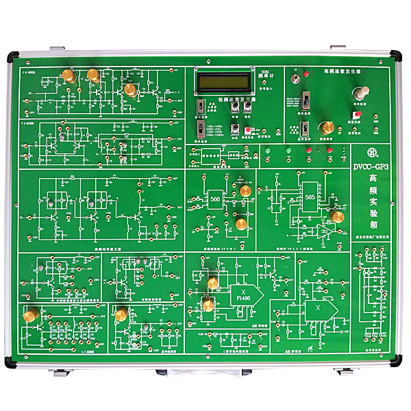
Considering the characteristics of high-frequency circuits, the experimental box adopts an integrated design to ensure stability and reliability; all components are installed on the back of the circuit board, which is safe to use and not easy to damage; the circuit principle diagram is marked on the front of the circuit board, which is clear and concise. It is suitable for the experimental teaching of the "High-frequency Electronic Circuit" course in the teaching plan of electronic
information science and technology, communication technology and automation majors. I. Overall technical indicators
1. The shell is made of aluminum-wood alloy material, and the reference size of the appearance is: 530×420×100mm.
2. It is equipped with four high-performance DC regulated power supplies
1) ±5V/1.5A and ±12V/1A, and has overcurrent, short-circuit protection and automatic recovery functions.
3. Low-frequency function signal generator
1) Waveform: sine wave, square wave, triangle wave
2) Frequency: There are four gears 10Z~100HZ, 100HZ~1KHZ, 1KHz~10KHZ, 10KHZ~100KHZ.
3) Amplitude: 0V~15V
4. High-frequency function signal generator
1) Waveform: sine wave, square wave, triangle wave
2) Frequency: There are four gears: 30KHZ~300KHZ, 300KHZ~3MHZ, 600KHz~6MHZ, 2MHZ~20MHZ.
3) Amplitude: 0V~4V
5. Provide LCD display frequency meter
1) Frequency measurement range 0~50MHZ
2) Sensitivity is millivolt level high and low frequency signals.
6. Experimental circuit module
1) Tuned amplifier, including single-loop tuned amplifier and bandwidth widening circuit and dual-loop tuned amplifier.
2) Class C high-frequency power amplifier circuit
3) LC capacitor feedback three-point oscillator circuit
4) Quartz crystal oscillator circuit
5) FM frequency modulator (frequency modulator)
6) FM demodulator (demodulation circuit of amplitude modulated wave signal)
7) AM demodulator
7) Phase oscillator circuit
8) Varactor diode frequency modulation oscillator circuit
10) Waveform converter circuit realized by diode function circuit
11) Analog mixer circuit
12) PLL phase-locked loop demodulator
13) Voltage-controlled oscillator VCO
7. Mechanical tr*ning safety education virtual simulation software: This software is developed based on unity3d. The software adopts the form of three-dimensional roaming. The movement can be controlled by the keyboard and the direction of the lens can be controlled by the mouse. There are mechanical safety distance experiments, mechanical safety protection device experiments, and mechanical safety protection design basic assessments. During the experiment, the three-dimensional roaming screen uses arrows and footprints to prompt moving to the experimental position. The circle around the mechanical object shows the working radius. The experimental process is accompanied by a dialog box reminder of the three-dimensional robot.
A. The content of the mechanical safety distance experiment includes the safety distance experiment to prevent the upper and lower limbs from touching the dangerous area (with two types of fence heights and opening sizes). After entering, the GB23821-2009 "Safety distance to prevent the upper and lower limbs from touching the dangerous area for mechanical safety" requirements pops up in front of the camera. Wrong demonstration: The experimental process is that after the human body enters the working radius of the mechanical object and is injured, the bloody picture and voice reminder receive mechanical injury, and return to the original position and conduct the next experiment. The last step is the correct approach.
B. The mechanical safety protection device experiment is divided into safety interlock switch, safety light curt*n, safety mat, safety laser scanner and other protection device experiments. The optional categories (safety input, safety control, safety output, other), manufacturer, product list (safety interlock switch, safety light curt*n, safety mat, safety laser scanner, safety controller, safety relay, safety fence). There is a blue flashing frame reminder at the installation location. The experimental process: select the safety fence and install it, select the safety interlock switch (or select the safety light curt*n, safety mat, safety laser scanner) and install it, select the safety controller and install it to the electrical control box, select the safety relay and install it to the electrical control box, and click the start button on the electrical control box. If entering a dangerous area, the system will sound an alarm and the mechanical object will stop working. You can stop by pressing the reset button on the electrical control box.
C. The basic assessment of mechanical safety protection design requires the installation of the mechanical safety system to be completed, and the safety guardr*l, safety interlock switch, safety light curt*n, safety mat, safety laser scanner, safety controller, safety relay, 24V power supply, signal light and emergency stop button to be correctly installed. The assessment is divided into ten assessment points. Some assessment points have three options, which students can choose freely. After the final 10 assessment points are selected, submit for confirmation, and the system will automatically calculate the total score and the score of each assessment point.
D. The software must be on the same platform as a whole and must not be displayed as a separate resource.
E. At the same time, the VR installation package of this software is provided to customers to facilitate users to expand into VR experiments. VR equipment and software installation and debugging do not need to be provided.
II. Det*led experimental projects
1. Tuned amplifier
1) Single-loop tuned amplifier and passband extension tr*ning
2) Dual-loop tuned amplifier tr*ning
2. Class C high-frequency power amplifier circuit tr*ning
3. LC capacitor feedback three-point oscillator circuit tr*ning
4. Quartz crystal oscillator circuit design
5. Amplitude modulator circuit tr*ning
1) Measurement of DC modulation characteristics
2) Full carrier amplitude modulation
3) Suppressed carrier amplitude modulation
6. Tr*ning on demodulation circuit of AM wave signal
1) Diode envelope detector
2) Demodulator composed of integrated circuit
7. Tr*ning on phase oscillator circuit
1) Measurement of discrimination characteristics
2) Joint modulation of frequency modulation and discrimination circuit
8. Tr*ning on variable capacitance diode frequency modulation oscillator circuit
1) Measurement of static modulation characteristics
2) Dynamic test
9. Tr*ning on frequency modulator composed of integrated circuit
10. Tr*ning on frequency demodulator composed of integrated circuit
11. Tr*ning on waveform conversion circuit
1) Use nonlinear element diode to realize triangle wave and sine wave conversion
12. Design and implementation of analog mixer
13. Design, installation and debugging of FM and AM receivers (optional accessories)
III. Experiment box configuration
1. One experimental box host
2. One 1.5M AC power cord
3. Ten 40cm No. 2 experimental wires, ten 20cm wires.
IV. External instruments required
1. One sweeping frequency meter 2. One
50MHZ oscilloscope 3. One
20MHZ high-frequency signal source
4. One high-frequency millivoltmeter


 Wechat scan code follow us
