DYSYX-DSP DSP experimental device
Release time:2024-07-03 05:30viewed:times
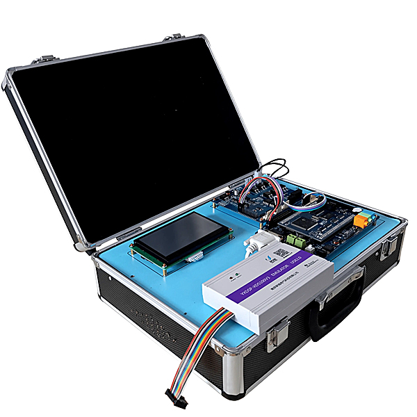
1. System Overview:
The DSP experiment box can use Texas Instruments (TI) TMS320VC54xx chips as the m*n processor (CPU), such as 5402, 5409, 5410, 5416 and other chips; it can also use ALTERA's Cyclone series FPGA chips, such as EP1C3. It can be used to implement various algorithms for digital signal processing, fully meeting the requirements of teaching experiments and secondary development. This product m*nly includes the expansion connector for all signals of the 54xx series chips, system clock, timer, HPI interface, standard serial port, high-speed AD/DA conversion, voice input and output interface circuit (AD50), digital waveform generator for dual-tone modulation DTMF frequency, traffic light module, DC motor drive module (can realize closed-loop control), stepper motor drive module, keyboard processing, LCD display, I/O input and output module, DSP processor and 51 series processor communication. This product is more suitable for control occasions such as voice processing, frequency conversion control, drag system, portable detection equipment, etc.
2. M*n functions:
M*n processor:
1. TMS320VC5402.
2. ALTERA FPGA chip: Cyclone EP1C3
Internal memory: 16KX16Bit internal dual-port memory, 4K on-chip ROM, external program/data memory expansion: 64Kx16Bit data memory with zero w*t cycle, 64Kx16Bit program memory; 32Kx8Bit system automatically loaded EPROM memory; 256K x16Bit FLASH memory. Voice input and power amplifier output: AD\DA (TMS320AD50C) with 16-bit synchronous buffer port, the highest sampling frequency is 22.05K. It has hardware filtering function, microphone input and speaker output function. UART serial interface: uses 16C550C chip, which complies with RS232 standard. Keyboard processing: 4X8 keyboard controlled by Lattice 1016. LCD display: uses 128X64 graphic LCD. High-speed AD/DA conversion: TLC7528, TLV1571.
HPI interface: Two interfaces are provided, which are connected to PC or other hosts respectively. DC motor closed-loop experiment. (51CPU is used to realize speed measurement and LCD display control, and DSP realizes speed control algorithm) I/O input and output module.
Power supply: 4 power supplies are provided: +5V, -5V, +12V, -12V, +3.3V and +1.8V are converted from +5V.
3. Virtual simulation software for mechanical tr*ning safety education: This software is developed based on unity3d. The software adopts the form of three-dimensional roaming. The movement can be controlled by the keyboard and the direction of the lens can be controlled by the mouse. There are mechanical safety distance experiments, mechanical safety protection device experiments, and basic assessments of mechanical safety protection design. During the experiment, the three-dimensional roaming screen uses arrows and footprints to prompt moving to the experimental position. The circle around the mechanical object shows the working radius. The experimental process is accompanied by a dialog box reminder of the three-dimensional robot.
A. The content of the mechanical safety distance experiment includes the safety distance experiment to prevent the upper and lower limbs from touching the dangerous area (with two types of fence heights and opening sizes). After entering, the GB23821-2009 "Safety distance to prevent the upper and lower limbs from touching the dangerous area for mechanical safety" requirements pops up in front of the camera. Wrong demonstration: The experimental process is that after the human body enters the working radius of the mechanical object and is injured, the bloody picture and voice reminder receive mechanical injury, and return to the original position and conduct the next experiment. The last step is the correct approach.
B. The mechanical safety protection device experiment is divided into safety interlock switch, safety light curt*n, safety mat, safety laser scanner and other protection device experiments. The optional categories (safety input, safety control, safety output, other), manufacturer, product list (safety interlock switch, safety light curt*n, safety mat, safety laser scanner, safety controller, safety relay, safety fence). There is a blue flashing frame reminder at the installation location. The experimental process: select the safety fence and install it, select the safety interlock switch (or select the safety light curt*n, safety mat, safety laser scanner) and install it, select the safety controller and install it to the electrical control box, select the safety relay and install it to the electrical control box, and click the start button on the electrical control box. If you enter the dangerous area, the system will sound an alarm and the mechanical object will stop working. You can stop it by pressing the reset button on the electrical control box.
C. The basic assessment of mechanical safety protection design requires the installation of the mechanical safety system to be completed, and the safety guardr*l, safety interlock switch, safety light curt*n, safety mat, safety laser scanner, safety controller, safety relay, 24V power supply, signal light and emergency stop button to be correctly installed. The assessment is divided into ten assessment points. Some assessment points have three options, which are freely selected by students. After the final 10 assessment points are selected, submit for confirmation, and the system automatically obt*ns the total score and the score of each assessment point.
D. The software must be the same platform as a whole and shall not be displayed as a separate resource.
E. At the same time, the VR installation package of this software is provided to customers to facilitate users to expand it into VR experiments. VR equipment and software installation and debugging do not need to be provided.
III. Experimental content:
A. DSP experiment:
Code Composer Studio V2.2, a DSP integrated debugging development environment, is used.
(I) Hardware experiment:
1. CPU basic instruction experiment
2. I/O port experiment.
3. Memory experiment
4. Interrupt experiment
5. Timer experiment
6. Synchronous serial port experiment
7. UART serial port and PC communication experiment
8. I/O analog serial port experiment
9. A/D experiment (TLV1571)
10. D/A experiment (TLC7528)
11. 8BitEPROM automatic loading experiment
12. PC HPI port loading experiment
13. Flash ROM experiment
14. Voice recording and
playback experiment (II)
15. ∏R filter design and experiment
16. Implementation of adaptive filter
17. Convolve convolution integral experiment
18. FFT fast Fourier transform
19. Sampling theorem and experiment
20. Correlation algorithm experiment
21. DCT discrete cosine transform
22. A-law compression and expansion experiment
B. FPGA experiment
Software environment: ALTERA QutartusII 3.0
1. Decoder design
2. Frequency divider design
3. Priority encoder design
4. Adder design
5. Modulus variable counter
6. Password lock design
7. Traffic light experiment
8. Fast multiplier design
9. Design and implementation of various filters


 Wechat scan code follow us
