Shanghai Daiyu Education Equipment Manufacturing Co., Ltd.
Language:


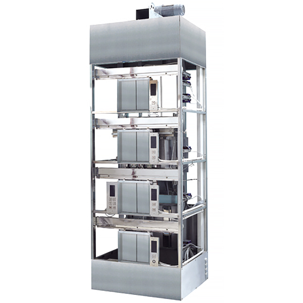


The four-story elevator simulation model can be used for elevator program teaching and troubleshooting practice in automation majors, and can also be used for elevator installation and m*ntenance demonstration operations in vocational technical schools.
1. M*n parameters:
1. Elevator car size: 600×500×560 (width×depth×height), outer dimensions.
2. Doorway size: 360×420 (width×height)
3. Peripheral dimensions of hoistway frame: 920×820×2900 (width×depth×height).
4. Equipment weight: about 300kg.
5. Traction machine power: 0.2KW. Voltage 380V or 220V.
6. Rated current: 0.86A.
7. Power supply: three-phase five-wire, 380V, 50HZ.
8. Frequency converter: Mitsubishi E740.
9. Programmable controller ( plc ): Japan Mitsubishi FX1N series.
10. Control mode: collective selection (JX).
11. Elevator landing: 4/4.
2. Structure Introduction
This model elevator m*nly consists of the following parts:
1. Shaft frame: equivalent to the building attached to the elevator, which provides support and fixes the guide r*ls. It is a steel frame structure.
2. Traction machine: Located at the top of the frame, it is the power device of the elevator. It is installed on two load-bearing beams. It m*nly consists of the following parts:
(1) Motor: three-phase induction motor, using variable frequency and voltage (VVVF) driving method. , when the elevator starts, the frequency converter causes the stator current frequency to start from a very low frequency and rise to the rated frequency according to the control requirements. When decelerating, the frequency converter causes the speed to smoothly decrease from the rated frequency to zero accordingly, achieving elevator leveling and ensuring elevator operation. Smooth, simulating the good comfort of a real elevator.
(2) Brake: The brake is only released when the elevator is powered on and running. When the elevator stops, it brakes and keeps the car position unchanged. The working voltage is AC220V.
(3) Reducer: It adopts gear reducer, which has the characteristics of high density, high efficiency and low noise.
(4) Traction pulley: The rope groove is a semicircular groove, which provides friction between the wire rope and the sheave.
3. Control panel:
(1) Frequency converter: According to the instructions given by the PLC, the frequency and voltage of the motor are modulated to make the motor run smoothly.
(2) Programmable controller (PLC): controls the operating status of the elevator,
makes a logical judgment on the elevator's position based on the internal selection signal, and then gives operating instructions to enable the elevator to respond to the call signal and stop in the forward direction. Reverse retention
signal, automatic door closing and other functions.
(3) Safety and door lock circuit: It is composed of a relay circuit. The emergency stop and door lock switch are on and off to determine whether the safety and door lock circuit is normal or not, so that the PLC can determine whether the elevator is in a safe state.
4. Guide r*ls: There are car guide r*ls and counterweight guide r*ls to ensure vertical movement of the car and counterweight.
5. Car: suspended by a traction wire rope, connected to the counterweight through the other end of the traction machine, running on the guide r*l, the car is equipped with automation, and the door is equipped with a ch*n switch. The elevator can only operate when the door is closed. There is also a safety switch on the door. Touch plate, when the car door encounters an obstacle during the closing process, the car door will open immediately.
6. Counterweight: connected to the car, its function is to balance the weight of the car.
7. Landing door: There is a door lock switch on the door. When the landing door is closed, the elevator can start.
8. Control box: Located on the left side of the front of the frame, it is a signal input device that simulates passengers selecting a floor in the car, including:
(1) Digital floor display: a seven-stripe digital display that displays the floor of the car.
(2) "1", "2", "3", "4", layer selection buttons.
(3) Close button.
(4) Direction indicator light: Indicates the elevator running direction.
(5) Power lock: switches the elevator power supply on and off, that is, the outbound call box on the first floor.
9. Deceleration signal system: It is composed of permanent magnet sensors and provides car parking floor position signals.
10. Terminal protection switch: The sensor provides the elevator operation terminal signal. When the elevator exceeds it, the safety circuit and power supply are cut off to ensure that the elevator does not exceed the terminal.
11. The model
in the comprehensive vocational skills integrated tr*ning virtual simulation system software can be rotated 360°, enlarged, reduced, and panned, and is equipped with universal interactive buttons: return, home page, and help. There are prompts during all virtual simulation tasks, and the software automatically checks the box after completing a task. There are experimental tasks 1 and basic three-dimensional above the tool library. (When the model is rotated, the XYZ space coordinate icon automatically follows the rotation.) A. Plane and three-dimensional: The experimental steps are divided into experimental tasks (text prompt tasks) - building models (drag and drop in the tool library The model is put into the three-projection plane system, and the projection is automatically displayed. There will be a prompt when the selection is wrong) - Change the posture (change by clicking the up, down, left and right arrows) - Select the projection (enter the answer interface, select the three-dimensional projection map completed at this time among the 6 items) )
B. Cutting three-dimensional: The experimental steps are divided into experimental tasks (text prompt tasks) - building the model (drag the model in the tool library into the three-projection plane system, and automatically display the projection) - labeling the projection situation (defining the three-dimensional projection map , select the corresponding label symbol in the 14 blank columns)
C. Intersecting three-dimensional: The experimental steps are divided into experimental tasks (text prompt tasks) - digging holes (select any digging model, you will be able to select in the XYZ space coordinates at this time On any surface, the model is switched at the same time, and a coordinate slider appears. According to the displacement of the slider, the model appears with a corresponding section plane) - aperture change (select aperture 1-4) - rear through hole - select projection (enter the answer interface, Select the three-dimensional projection picture completed at this time among the 8 items)
2. Assembly
A, assembly assembly: The experimental steps are divided into experimental tasks (text prompt tasks) - Select the assembly model (8 models av*lable) - Assemble the assembly (Select the tool library model according to the selected model and drag and drop the combination) - Sectioning the assembly (you can select any surface in the XYZ space coordinates, the model is switched at the same time, and a coordinate slider appears. According to the displacement of the slider, the model appears corresponding horizontal section plane)—select the side projection (enter the answer interface and select the correct side projection among the 3 items based on the known front and horizontal projections)
B. Combination image reading: The experimental steps are divided into experimental tasks (text prompts Task)—Select the combination section view (8 types of pictures are av*lable)—Build the combination model (select the tool library model according to the selected model and drag and drop the combination)—Section the combination (you can select any surface in the XYZ space coordinates, model Switch at the same time, and a coordinate slider will appear. According to the displacement of the slider, the model will appear with a corresponding section plane) - Select the left view (enter the answer interface, select the correct left view among the 3 items based on the known m*n view and top view) )
3. Assembly
A, mechanical transmission mechanism : 8 types of mechanisms (worm gear, rack and pinion, screw transmission, out-of-plane meshing gear, in-plane meshing gear, space spur bevel gear, belt drive , ch*n drive) optional, After selecting, the model will appear in the toolbar. You can drag and drop the models freely to combine them. After the combination is completed, you can operate the model. Each mechanism comes with an introduction, video demonstration, and drawing instructions. There are 6 questions in the answering interface, and each question has 4 options.
B. Gear oil pump: Select the tool library model according to the prompts to gradually build the model. You can choose the introduction, drawing method, and animation principle (the internal movement principle of the model is visible) to learn. There are 2 questions in the answering interface, each with 4 options.
C. Mechanical mechanism construction: 2 types of mechanisms (2-DOF robotic arm, 3-DOF robotic arm). Select the tool library model according to the prompts to gradually build the model. After the combination is completed, the model can be operated. Each mechanism comes with an introduction and video demonstration. . There are 2 questions in the question-answering interface (which can only be entered after both models have been built), each with 4 options.
3. Functions and related operations of the model elevator:
1. Normal operating procedures
(1) Connect the three-phase power supply.
(2) Open the power lock on the calling box, and the floor should be displayed. The elevator can automatically close the door and respond to outbound calls. After selecting the floor on the control box, the door must be closed before it can run. At this time, the outbound call signal in the forward direction can be stopped, and the reverse call signal can be ret*ned.
(3) Hall call: The elevator can automatically respond to the signal and stop in the forward direction. In the reverse direction, it can automatically answer after completing the previous command.
(4) Parking: After the elevator stops at the ground floor and closes the door, pull the power key of the call box to "off" to cut off the elevator power and stop working.
2. M*ntenance jog operation.
Pull the "Normal"-"M*ntenance" switch in the control panel to the "M*ntenance" state.
At this time, the elevator will only run inching, but the safety circuit and door lock are still effective.
Press the "Up" or "Down" button, and the elevator will run inching. Move up or down. This operation
is used for elevator m*ntenance or testing the terminal limit function. After leveling
the elevator with inching operation , turn the selector switch to "Normal" and the elevator will resume normal operation.
4. M*ntenance instructions: When performing m*ntenance work on the model elevator, the three-phase power supply must be turned off:
1. Lubrication instructions:
(1) Traction machine reduction box: inspect once every six months.
(2) Car guide r*l: Apply a small amount of engine oil.
Counterweight guide r*l: Apply a small amount of calcium-based grease.
(3) Hall door and car door guide r*ls: Apply a small amount of engine oil.
Special note: The wire rope cannot be lubricated.
2. D*ly m*ntenance points:
(1) When the elevator is running, pay attention to observe whether the overall structure vibrates abnormally, whether the traction machine makes abnormal noise, oil leakage, and whether there is vibration when the car or counterweight is running.
(2) Check whether the traction machine brake can be opened normally.
(3) Check whether each hall door lock operates normally and whether there is any jamming. If necessary, add a small amount of machine lubrication to the pin.
(4) Check whether the door machine opens and closes normally and whether the door can be opened in place. If necessary, adjust the position of the swing lever and add engine oil to the pin.
(5) Electrical inspection:
Check whether each fuse is blown out, check whether each travel switch and sensor operate normally, and check whether each door lock contact is well connected.
5. Simple troubleshooting:
1. Protection When the external power supply has the wrong phase or lacks a phase, the phase sequence protection relay in the control panel acts, and the indicator light is red. At this time, you can change the phase sequence or check whether there is a phase lack.
2. If the traction machine brake cannot be opened, check:
(1) Whether the 220V brake circuit fuse is blown.
(2) Whether there is electricity at 220V.
3. The door lock circuit is blocked: Check whether the door lock contacts are in good contact, and use a multimeter to measure the contact resistance.
4. The safety circuit is blocked: Check whether the safety switch of the entire elevator is closed and whether the switch is normal.
5. The door machine is too slow or too fast: You can adjust the door machine speed regulating resistance or check whether the door machine carbon brushes are worn.
6. Inaccurate leveling: The position of the leveling sensor can be adjusted.
6. Control method description:
The above control method is switch control, that is, the elevator provides deceleration and leveling signals from the switch (sensor) in the shaft. According to the latest trend of elevator development, the digital control method of new technology is used. That is, a rotary encoder is used to provide digital pulses, and then the PLC (programmable controller) counts and processes the signals to obt*n the position of the car and send out deceleration and leveling signals. After adopting this technology, many switches in the shaft can be omitted, improving the stability of the elevator and reducing faults. This simulated elevator can convert the above two control methods through the transfer switch (HK), that is, the conversion of switch value and digital value.
This simulated elevator PLC has two sets of programs stored in it, which can be switched freely through the transfer switch (HK). When the transfer switch is placed in
switch control, the switch in the shaft provides instructions and the digital signal is blocked. When the transfer switch is placed in digital
control, the number of pulses provided by the rotary encoder is used as a signal processed by the PLC, and the switching signal is blocked at the same time.
7. Fault description:
1. Sensor f*lure:
Fault 1.: The forced deceleration sensor on GU (324-310) is damaged. The elevator cannot go up normally but can go down.
Fault 2: The forced deceleration sensor under GD (325-310) is damaged and the elevator cannot go down normally but can go up.
Fault 3: SW (264-310) upper limit sensor is damaged and the elevator cannot go up but can go down.
Fault 4: XW (265-310) lower limit sensor is damaged and the elevator cannot go down but can go up.
Fault 5: KAB (278-310) touch plate switch f*ls, safety touch plate is invalid
Fault 6~7: AK (268-310); AG (269-310) door opening and closing button f*ls and cannot open or close the door.
Fault 8~11: 1AS (1A-310); 2AS (2A-310); 3AS (3A-310)
4AS (4A-310); the internal selection button f*ls and the selected floor is registered.
Fault 12~14: 1SA (1S-310); 2SA (2S-310); 3SA (3S-310)
selected floor button signal cannot be registered. The up call button f*ls,
fault 15~17: 2XA (2X-310); 3XA (3X-310); 4XA (4X-310) down call button f*ls, and the selected floor button signal cannot be registered.
Fault 18~19: PKM (237~301); PGM (243-301) door in-position
switch is damaged and cannot be closed, causing the door opening or closing relay to f*l to close.
2. Contact, switch, button f*lure:
Fault 20~23: 1TS (1T1, 2T1); 2TS (1T2, 2T2); 3TS (1T3, 2T3)
4TS (1T4, T4); hall door interlock switch circuit f*lure, The elevator doesn't work.
Fault 24: SQF (111, 301) car door lock switch is faulty and the elevator cannot run.
Fault 25~27: SJN (301, 131); SAQ (129, 127); SDS (125, 123)
safety circuit and electrical circuit f*lure, the elevator cannot operate.
Fault 28~29: KDX (115~113); JR (113~101) phase sequence and thermal relay f*lure, the elevator cannot operate.
Fault 30: DYJ (261-310) safety circuit relay contacts are in poor contact, and the elevator cannot perform any operations.
Fault 31: MSJ (262-310) door interlock circuit relay contacts are in poor contact, the elevator cannot run but the door can be opened and closed.
Fault 32~33: KMJ (582-301); KMJ (304-482) door opening circuit has poor contact with the door opening
relay contact, resulting in the door motor having no power and unable to open the door.
Fault 34~35: GMJ (482-301); GMJ (304-682) close circuit closed
relay contact is bad, causing the door motor to have no power and cannot close the door.
Fault 36~37: KMG (241-244); GMJ (235-239).
The normally closed contact of the door opening relay in the door opening and closing relay circuit has poor contact, causing the door opening relay or door closing
relay to f*l to close.
3. PLC output relay f*lure:
Fault 38~41: Y10 (1R-304); Y11 (2R-304); Y12 (3R-304)
Y1 (4R-304), the internal selection button light and the output button light do not light up.
Fault 42~44: Y17 (A-304), Y20 (B-304), Y21 (C-304).
The floor display output relay is damaged and the corresponding floor cannot be displayed.
Fault 45~48: Y4 (11,J4), Y5 (11,J5), Y6 (11, J6) Y7 (11, J7) PLC output fault, causing the inverter to malfunction or f*l to operate. A: Each fault point is set outside the switch.
B: Each fault point is led to the fault terminal block. C: All faulty switches are connected in series.
D: Troubleshooting example description:
Take fault 1 as an example:
When the fluctuation fault occurs in the rotor switch 1, the elevator cannot move up normally. At this time, you only need to short-circuit the wire number 324 (terminal row 2) to the same wire number 324 (terminal row 4), and the elevator can operate normally. After restoring the twist switch 1, please remove the short wire.
8. Safety precautions:
1. The system must be reliably grounded, and the resistance of the ground wire must comply with relevant national regulations and be no more than 4Ω.
2. The line insulation resistance should be greater than 0.5MΩ.
3. The door lock cannot be operated by short-circuiting.
4. Unless you have a thorough understanding of the functions of each parameter of the PLC and frequency converter, the program and parameters must not be changed.
5. The elevator power supply system should be set up independently and should not be shared with welding machines, high-frequency furnaces and other equipment. Other equipment that is susceptible to magnetic interference should also be kept away from the elevator control panel.
6. When you find that the traction machine is particularly hot, smoking, or making abnormal noises, you should turn off the power immediately and troubleshoot before continuing to use it.
9. Electric control panel
The electronic control panel is also equipped with internal selection buttons and floor display. There is a hidden fault function board behind the electronic control panel.
|
VVVF variable frequency elevator electrical component code list |
||||||
|
serial number |
code name |
Name and specification |
Material |
New assembly code |
quantity |
Remark |
|
1 |
KMJ,GMJ |
door switch relay |
MY4 DC24V |
Control panel |
2 |
|
|
2 |
DYJ |
voltage relay |
MY4 DC24V |
Control panel |
1 |
|
|
3 |
MSJ |
door interlock relay |
MY4 DC24V |
Control panel |
1 |
|
|
4 |
RF1-RF2 |
*r switch |
|
Control panel |
1 |
|
|
5 |
QC |
m*n contactor |
GMC-12 AC220V |
Control panel |
1 |
|
|
6 |
GH |
Power contactor |
GMC-12 AC220V |
Control panel |
1 |
|
|
7 |
1A-5A |
Car floor selection command button |
AK-01 |
Inside the sedan |
5 |
5th floor |
|
8 |
1R-5R |
Layer selection command light |
|
Inside the sedan |
5 |
|
|
9 |
AK,AG |
door open button |
AK-01 |
Inside the sedan |
2 |
|
|
10 |
T T |
up and down buttons |
|
Control panel |
2 |
|
|
11 |
RF3 |
*r switch |
|
Control panel |
1 |
|
|
12 |
FM/CHD |
Overload buzzer |
DC24V |
Inside the sedan |
1 |
|
|
13 |
KSD,XD |
Up and down indicator lights |
DC24V |
Inside the sedan |
2 |
|
|
14 |
SMJ/MK |
M*ntenance switch |
|
Control panel |
1 |
|
|
15 |
SB(KAB) |
Safety touch panel switch |
|
car |
1 |
|
|
16 |
SAC |
safety gear switch |
|
car |
1 |
|
|
17 |
SQF |
Car door interlock switch |
|
car |
1 |
|
|
18 |
*1--*48 |
point of f*lure |
|
Control panel |
48 |
|
|
19 |
PU |
Door drive bistable switch |
|
car top |
2 |
|
|
20 |
GU |
Up and down strong alkaline return speed |
|
car top |
2 |
|
|
twenty one |
DZ1 |
Car emergency lighting |
|
car top |
1 |
Options |
|
twenty two |
FS |
Car fan |
|
car |
1 |
|
|
twenty three |
CH |
overload switch |
|
car bottom |
1 |
|
|
twenty four |
M1 |
door motor |
|
Automatic door machine |
1 |
|
|
25 |
PKM |
Door open switch |
|
Automatic door machine |
1 |
|
|
26 |
PGM |
Close door limit switch |
|
Automatic door machine |
1 |
|
|
27 |
SG |
door closing deceleration switch |
LX028 |
Automatic door machine |
2 |
|
|
28 |
M |
AC motor |
|
engine room |
1 |
|
|
29 |
DZ |
Brake coil |
AC220V |
engine room |
1 |
|
|
30 |
SW XW |
Upper and lower limit switches |
|
Shaft |
2 |
|
|
31 |
SDS |
Pit rope breaking switch |
|
Shaft |
1 |
|
|
32 |
SJK,XJK |
Upper and lower limit switches |
|
Shaft |
2 |
|
|
33 |
1G~4G |
Up memory light |
DC24V |
Shaft |
2 |
|
|
34 |
1SA~4SA |
call button |
|
Shaft |
2 |
|
|
35 |
2C~5C |
Lower recall memory light |
DC24V |
Shaft |
2 |
|
|
36 |
2XA~54XA |
Call down button |
|
Shaft |
2 |
|
|
37 |
ST1~ST5 |
Hall door interlock contact |
|
Shaft |
3 |
|
|
38 |
ikB |
Base station key switch |
|
Shaft |
1 |
|
|
39 |
WSK |
driver/auto switch |
|
bridge box |
1 |
|
|
40 |
1PG |
Deceleration sensor |
|
Shaft |
5 |
|
|
41 |
HK |
Digital-to-analog conversion switch |
|
Electrical cabinet |
1 |
|
|
42 |
D2 |
24V silicon rectifier bridge |
|
Electrical cabinet |
1 |
|
|
43 |
SJU |
Electric cabinet emergency stop switch |
|
Electrical cabinet |
1 |
|
|
44 |
KDX |
Phase sequence protection relay |
|
Electrical cabinet |
1 |
|
 Wechat scan code follow us

24-hour hotline+86 18916464525

Phone18916464525
ADD:Factory 414, District A, No. 6, Chongnan Road, Songjiang Science and Technology Park, Shanghai ICP: Sitemap