DYDT-XL Elevator Electrical Circuit Experiment Platform
Release time:2024-06-28 08:30viewed:times
I. General requirements
1. The model elevator has 4 floors and 4 stations, and is composed of a simulated shaft frame, a car, a counterweight, a traction machine, an elevator door, a door motor , an external call box at each floor station, and m*n safety devices, which are fixed on the side of the test bench . The simulated shaft frame needs to be equipped with floor sensors and leveling sensors (similar to actual elevators) for detecting the position of the car, and their wiring terminals are connected to the plug-in holes of the simulated shaft frame. The shaft frame uses metal materials as the m*n support and is closed with organic glass.
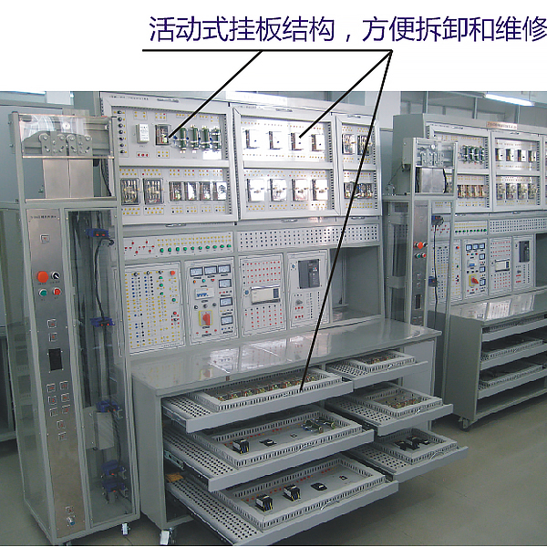
The equipment adopts a desktop structure, with a movable drawer electrical board. Each drawer board is equipped with a public wiring board (bus type wiring method, the number of bus connection points must reach more than 120 points), and the drawer electrical boards are connected by industrial tank ch*ns. The public drawer board connection uses a real elevator multi-core accompanying cable.
2. Model elevator traction system
The model elevator traction system is fixed on the test bench and consists of a three-phase AC motor, a reducer, a fuse, a thermal relay, a phase sequence and phase f*lure protection relay, and an AC contactor for forward and reverse control. The rated voltage of the motor is 380V.
3. Elevator door control system
The elevator door control system consists of a door opening and closing control circuit and a door speed adjustment circuit. The door motor is fixed on the simulated shaft frame and powered by 24V DC. It is controlled by relays and arranged in an independent hanging board manner, which can realize manual or automatic control of the door.
II. Requirements Overview
1. The elevator electrical circuit disassembly and assembly tr*ning and assessment device is used to complete the installation of the power supply and distribution
lines of the elevator tr*ning room and various tr*ning equipment. 2. Each set of tr*ning equipment system includes the following equipment with relay control:
(1) A four-story station elevator model including shaft information detection, which is used to simulate the mechanical movement of the elevator car and door.
(2) A model elevator traction system, which is used to drive the car in the elevator model. The traction system should be able to simulate the driving operation of a single-speed elevator and can simulate the driving operation of a double-speed elevator when combined with a frequency converter.
(3) The elevator door opening and closing control system with relay control can use both manual control and automatic control to drive the elevator door, which is used for students to conduct practical tr*ning on line connection, fault analysis and m*ntenance of the elevator door opening and closing control system. (4) AC single-speed and AC dual-speed elevator control systems with relay control are used for students to conduct practical tr*ning on line connection, fault analysis and m*ntenance of relay control systems of various types of elevators.
(5) AC single-speed and AC dual-speed elevator control systems and elevator door opening and closing control systems with inverter control are used for students to conduct practical tr*ning on line connection, program compilation, fault analysis and m*ntenance of various types of elevator control systems.
(6) Power supply system is used to provide power to the elevator's traction system and control system. In addition to all the equipment of the tr*ning equipment system, the teaching demonstration equipment must also be equipped with a tr*ning power control system, and consider the convenience of the purchaser to configure the teaching demonstration equipment. Among them, the tr*ning power control system is used to monitor the power supply of all tr*ning equipment systems, so that teachers can independently control the power supply of each student tr*ning system during the teaching process.
3. Wireless touch intelligent assessment system: It adopts the digital integrated circuit board with the latest MCU technology RAM processing chip and the matching wireless fault setting control system. The system is stable and not easy to be infected by viruses. The control module (PC control terminal or handheld mobile control terminal) and the drive module (intelligent fault setting drive box) are separated to avoid complex wiring interference with the controller, making the system more reliable. The drive module has a built-in intelligent fault setting control system, equipped with a dedicated new wireless data transmission module (pluggable) and an RS232 serial communication interface, which can communicate wirelessly and via RS232 wired communication. The handheld mobile control terminal uses a 7-inch high-definition color LCD touch screen, a Chinese menu-style touch operation interface, and a friendly human-computer dialogue. The handheld mobile control terminal can control any tr*ning equipment with a drive module. The handheld mobile control terminal can be operated as a single machine when it is not connected to the Internet. When the tr*ning equipment with the drive module is wirelessly networked, the handheld mobile control terminal can be wirelessly connected to the Internet as a network terminal, which can be used as an operating terminal for students to log in to the tr*ning and assessment, and as an operating terminal for teachers to log in to set questions. Tr*ning and assessment can be carried out through the PC control terminal or the handheld mobile control terminal. The teacher and student interfaces are separated. The teacher enters the teacher interface with a password to set questions, and the students answer questions in the ordinary interface. (Note: The schematic diagram of the fault setting and troubleshooting interface for teachers and students is exactly the same as the schematic diagram of the equipment panel) You can freely set any common fault, including: line break, short circuit to ground, poor contact, occasional fault phenomenon. Each set of driver modules can set 8 open circuit faults of large current 5A, 16 open circuit, poor, occasional, short circuit and other faults of small current 2A signal channels, a total of 24 fault settings. According to the needs, 64 open circuit faults of large current 5A and 128 open circuit, poor, occasional, short circuit and other faults of small current 2A signal channels can be expanded to set, a total of 192 fault settings. The number of fault setting points and the type of fault setting can be adjusted according to user requirements. All tr*ning equipment equipped with driver modules can be wirelessly networked through the built-in dedicated new wireless data transmission module to achieve remote centralized management. Users can choose to form a network with the wireless fault setting control system of other tr*ning equipment through wireless or RS-232 serial communication, and control the fault setting, troubleshooting, parameter setting, remote start, information feedback, assessment and scoring of each tr*ning equipment through the m*n control computer.
4. Virtual simulation system for comprehensive integrated tr*ning of vocational skills The model
in the software can be rotated 360°, enlarged, reduced, and translated, and has universal interactive buttons: return, home page, help. There are prompts for all virtual simulation task processes, and the software automatically ticks after completing a task. There are experimental tasks 1 and basic solids above the tool library (the XYZ space coordinate icon automatically rotates with the rotation when the model is rotated.) A. Plane solids: The experimental steps are divided into experimental tasks (text prompt tasks) - build models (drag the model in the tool library to the three-projection surface system, and the projection will be automatically displayed. There will be prompts when the selection is wrong) - change posture (change by clicking the up, down, left, and right arrows) - select projection (enter the answering interface, and select the three-dimensional projection diagram completed at this time from the 6 items) B. Cutting solids: The experimental steps are divided into experimental tasks (text prompt tasks) - build models (drag the model in the tool library to the three-projection surface system, and the projection will be automatically displayed) - mark the projection situation (mark the three-dimensional projection diagram, and select the corresponding marking symbol in the 14 blank columns)
C. Intersecting solids: The experimental steps are divided into experimental tasks (text prompt tasks) - digging holes (select any digging hole model, then you can select any surface in the XYZ space coordinates, the models will switch at the same time, and a coordinate slider will appear. According to the displacement of the slider, the model will have a corresponding degree of cross-section) - aperture change (select 1-4 apertures) - rear through hole - select projection (enter the answering interface, and select the completed three-dimensional projection diagram at this time in 8 items)
2. Assembly
A. Assembly assembly: The experimental steps are divided into experimental tasks (text prompt tasks) - select the assembly model (8 models can be selected) - assemble the assembly (select the tool library model according to the selected model and drag and drop the assembly) - section the assembly (you can select any surface in the XYZ space coordinates, the models will switch at the same time, and a coordinate slider will appear. According to the displacement of the slider, the model will have a corresponding degree of cross-section) - select side projection (enter the answering interface, based on the known front and horizontal projection diagrams, select the correct side projection diagram in 3 items)
B. Assembly drawing reading: The experimental steps are divided into experimental tasks (text prompt tasks) - select the assembly section view (8 types of drawings can be selected) - build the assembly model (select the tool library model according to the selected model and drag and drop the combination) - cut the assembly (you can select any surface in the XYZ space coordinates, the model will switch at the same time, and a coordinate slider will appear. According to the displacement of the slider, the model will appear with a corresponding degree of section) - select the left view (enter the answer interface, according to the known m*n view and top view, select the correct left view from the 3 items)
3. Assembly
A. Mechanical transmission mechanism : 8 mechanisms (worm gear, gear rack, spiral transmission, plane external meshing gear, plane internal meshing gear, space spur bevel gear, belt drive , ch*n drive) are optional. After selecting, the model will appear in the toolbar. Drag the model freely to combine. After the combination is completed, the model can be operated. Each mechanism comes with an introduction, video demonstration, and drawing method. There are 6 questions in the answer interface, and each question has 4 options.
B. Gear oil pump: Select the tool library model according to the prompts and build the model step by step. You can choose to learn the introduction, drawing method, and animation principle (the internal movement principle of the model can be visualized). There are 2 questions in the answering interface, and each question has 4 options.
C. Mechanical mechanism construction: 2 mechanisms (2-DOF robotic arm, 3-DOF robotic arm). Select the tool library model according to the prompts and build the model step by step. After the combination is completed, you can operate the model. Each mechanism has an introduction and video demonstration. There are 2 questions in the answering interface (you must complete the construction of both models to enter). There are 4 options for each question.
III. Functional requirements
1. Laboratory cabinet bench.
(1) The laboratory cabinet uses metal material as the m*n bracket, and the overall size is controlled within 1750*500*1950mm.
(2) The electrical board is installed in the cabinet.
2. Power supply
The practical power supply system provides the power required for the normal operation of the equipment, and is designed with instruments, indicator lights, protection measures, etc. The power supply of the student laboratory bench is centrally controlled (on or off) by the m*n control box, and a m*n switch, overload protection, leakage protection and indicator lights are set. The power supply system needs to provide three-phase AC 380V, single-phase AC 220V, DC 110V, 24V and other power supplies, which are controlled by independent switches, and the indicator light shows its connection status. The voltage value is monitored by the voltmeter configured on the working surface of the experimental table; the power supply terminal is connected to the plug hole on the working surface of the experimental table through internal wiring, and marked on the working surface.
3. AC single-speed elevator control system
The AC single-speed elevator control system consists of related link circuits such as emergency stop circuit, door interlock circuit, external call circuit, internal selection circuit, car position detection circuit, automatic directional circuit and stop layer circuit. It is controlled by relay mode and arranged in an independent hanging board mode, which can realize the drive control of AC single-speed elevators at 2 to 4 floors.
4. AC double-speed elevator control system The
AC double-speed elevator control system consists of two independent hanging boards. Hanging board 1 includes: internal selection circuit, car position detection circuit, automatic directional circuit and door switch control circuit; hanging board 2 includes: fast start circuit, operation circuit, speed change circuit and leveling circuit. It adopts 110V DC power supply and is controlled by relay, which can realize the drive control of AC double-speed elevators at 2 to 4 floors.
5. Inverter elevator control system
Inverter elevator control system, the inverter host adopts a well-known brand (0.4KW or above) and is powered by AC 380V. It is fixed on the working panel of the experimental table, and the power supply is connected to the plug hole of the working panel through the internal lead, which can realize the drive control of AC single and double-speed elevators at 2 to 4 floors.
6. Wiring requirements
The wiring terminals of all components on each independent hanging board must be connected to the plug hole of the hanging board working surface through the internal lead, and connected to each other or connected to the equipment plug hole on the working surface of the experimental table through the wire with double plug connector (completed by students). The plug hole and wire of the m*n circuit should be one specification larger than the control circuit to facilitate distinction.
7. Printing requirements
On the working surface of the experimental table and the independent hanging board, all equipment devices are printed according to the requirements of the circuit drawing, including device symbols, coils and terminal numbers.
★8. Equipment Technology
(1) All electrical connections should be machine-coded with wire numbers that match the drawings.
(2) The control console and electrical board are clearly printed with component names, contact names, jack names, etc.
(3) The common lines in the electrical board, the shaft signal lines, and the connecting lines between the upper and lower hanging boards are reliably connected. (4)
When delivered to the user, all hanging boards (including the shaft rack) of the test bench are connected to form a complete system and powered on one by one for demonstration. (One part is connected to the dual-speed operation mode, and the other part is connected to the operation mode).
(5) All electrical boards should be convenient and flexible to disassemble and assemble, and easy to m*nt*n.
(6) The layout of the components of the control console and electrical board should be reasonable and beautiful.
(7) The experimental connecting wires are distinguished by different colors: for example, AC220 uses red, DC110V uses green, etc.
(8) Relays of various specifications use indicator lights to display the power-on and power-off status.
(9) The connecting wire plug connectors can be stacked.
(10) The internal selection button, the external call button, the door opening/closing button, etc. use actual elevator components, and the layout is beautiful and reasonable.
(11) The safety touch panel APK is simulated by a button and installed at the car door position.
(12) The test bench and the shaft frame have grounding wires and are well grounded.
(13) The shaft frame is wired with cables or sheathed wires.
(14) The shaft frame is enclosed with plexiglass.
(15) The contacts of electrical components in the shaft frame cannot be exposed.
(16) The car door is made of st*nless steel.
9. Practical tr*ning course content
Experiment 1 Understanding the overall structure of the elevator.
Experiment 2 Understanding the structure of the elevator car door.
Experiment 3 Use of elevator contacts, switches, and buttons.
Experiment 4 Operation tr*ning of the elevator safety protection system.
Experiment 5 Analysis and operation tr*ning of elevator sensors.
Experiment 6 Operation and debugging tr*ning of elevator door opening and closing circuits.
Experiment 7 Analysis and operation tr*ning of elevator safety door lock circuits.
Experiment 8 Tr*ning of elevator car position detection.
Experiment 9 Debugging tr*ning of elevator internal selection circuits.
Experiment 10 Debugging tr*ning of elevator external call circuits.
Experiment 11 Tr*ning of elevator automatic leveling and up and down circuits.
Experiment 12 Tr*ning of elevator directional speed change circuits.
Experiment 13 Tr*ning of elevator express operation circuits.
Experiment 14: Tr*ning on elevator m*ntenance and slow car circuit.
Experiment 15: Understanding the structure of elevator electrical control system.
Experiment 16: Tr*ning on elevator control system debugging.
Experiment 17 : Tr*ning on basic plc
instructions. Experiment 18: Tr*ning on PLC programming.
Experiment 19: Setting inverter parameters.
Experiment 20: Operation of inverter speed regulation.
Experiment 21: Tr*ning on single-speed elevator whole machine operation debugging.
Experiment 22: Tr*ning on double-speed elevator whole machine operation debugging.


 Wechat scan code follow us
