Shanghai Daiyu Education Equipment Manufacturing Co., Ltd.
Language:


| Serial number | name | quantity | unit | Remark |
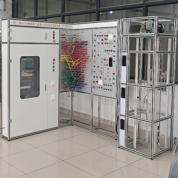
| 1 | Bracket | 1 | tower | High-grade aluminum profiles |
| 2 | M*n power box | 1 | tower | Circuit breakers, *r switches, indicator lights, lighting switches and sockets, etc. |
| 3 | Microcomputer control cabinet | 1 | tower | Integrated controller (NICE1000), *r switch, phase f*lure and phase sequence protection relay, counter, contactor, switching power supply, transformer, brake resistor, terminal block, up and down buttons, emergency stop and m*ntenance switch, etc. |
| 4 | Safety plug terminal board | 2 | piece | |
| 5 | Outbound call display board | 3 | piece | |
| 6 | Traction machine simulator | 1 | set | Three-phase asynchronous motor and encoder |
| 7 | Hoistway Simulator | 1 | set | Upper and lower limits, upper and lower limits, upper and lower deceleration, upper and lower emergency stop, safety clamp, leveling, door opening and closing limits, overload, and lighting switch |
| 8 | Pit Simulator | 1 | set | Tensioner and lighting switch, lighting, socket |
| 9 | Floor Simulator | 3 | set | Door lock, fire and elevator lock switches, up and down elevator call buttons |
| 10 | Computer room simulation devices | 1 | set | Speed limiter and turning switch |
| 11 | Car Simulator | 1 | set | Lighting, fans and light curt*ns |
| 12 | Car control box simulation device | 1 | set | Door opening and closing, floor, emergency stop, m*ntenance, up and down, lighting, fan, driver and direct drive switch |
| 13 | Car top control box analog device | 1 | set | Up/down and common buttons, emergency stop, m*ntenance and lighting switches, lighting, sockets |
| 14 | Operation status indication | 1 | set | Door opening, opening and closing, starting and braking |
| 15 | Safety plug | 1 | set | |
| 16 | Electrical m*ntenance tools | 1 | set | Multimeter and electric pen, etc. |
| 17 | Random Information | 1 | share | Tr*ning instructions and related drawings, etc. |
 Wechat scan code follow us

24-hour hotline+86 18916464525

Phone18916464525
ADD:Factory 414, District A, No. 6, Chongnan Road, Songjiang Science and Technology Park, Shanghai ICP: Sitemap