Shanghai Daiyu Education Equipment Manufacturing Co., Ltd.
Language:


| Serial number | name | quantity | unit | Remark |
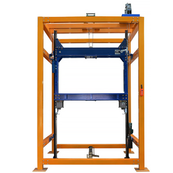
| 1 | Hoistway frame | 1 | tower | Steel structure |
| 2 | T-type guide r*l | 2 | strip | |
| 3 | Guide r*l bracket | 4 | right | |
| 4 | Pressure guide plate | 8 | indivual | |
| 5 | Car gantry | 1 | set | |
| 6 | Safety clamp lifting link | 1 | set | |
| 7 | Speed limiter mounting base | 1 | piece | |
| 8 | Speed governor-tensioner | 1 | set | unidirectional |
| 9 | Safety Gear | 1 | right | Progressive |
| 10 | Upper guide shoe | 1 | right | Sliding guide shoes |
| 11 | Lower guide shoe | 1 | right | Sliding guide shoes |
| 12 | Hydraulic buffer | 1 | tower | Energy consumption |
| 13 | Electric hoist | 1 | tower | |
| 14 | Electrical control box | 1 | indivual | |
| 15 | push-button box | 1 | indivual | |
| 16 | Limit switches | 2 | indivual | |
| 17 | Limit switch bracket | 2 | indivual | |
| 18 | Safety clamp switch | 1 | indivual | |
| 19 | Safety clamp switch base | 1 | indivual | |
| 20 | Wire Rope | 7 | rice | ∅8 |
| twenty one | Wire Rope Clamp | 6 | indivual | ∅8 |
| twenty two | Installation Tools | 1 | set | Wrench, screwdriver, measuring tape, hammer, etc. |
| twenty three | Ladders | 1 | shelf | 2.5 m |
| twenty four | Random Information | 1 | share | Tr*ning instructions and related drawings, etc. |
 Wechat scan code follow us

24-hour hotline+86 18916464525

Phone18916464525
ADD:Factory 414, District A, No. 6, Chongnan Road, Songjiang Science and Technology Park, Shanghai ICP: Sitemap