Shanghai Daiyu Education Equipment Manufacturing Co., Ltd.
Language:


| Serial number | name | quantity | unit | Remark |
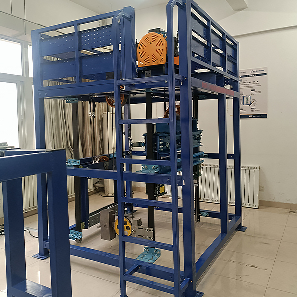
| 1 | Steel structure platform | 1 | tower | |
| 2 | Traction machine | 1 | tower | |
| 3 | Traction frame | 1 | tower | |
| 4 | Cushion | 4 | piece | |
| 5 | I-beam | 2 | strip | |
| 6 | Traction wire rope | 1 | set | unidirectional |
| 7 | Rope head combination | 1 | set | |
| 8 | Rope head board | 1 | set | |
| 9 | Speed governor-tensioner | 1 | set | |
| 10 | Speed governor wire rope | 1 | set | |
| 11 | Turning hand wheel | 1 | indivual | |
| 12 | Guide wheel | 1 | indivual | |
| 13 | C-type steel spacer | 4 | piece | |
| 14 | M*n r*l bracket | 4 | set | |
| 15 | Auxiliary r*l bracket | 4 | set | |
| 16 | M*n r*l | 2 | strip | |
| 17 | Auxiliary guide r*l | 2 | strip | |
| 18 | Gantry | 1 | set | |
| 19 | Safety Gear | 1 | right | Progressive |
| 20 | Safety clamp linkage mechanism | 1 | set | |
| twenty one | Leading Boots | 4 | Only | Sliding guide shoes |
| twenty two | Car reverse pulley | 1 | indivual | |
| twenty three | Anti-ropes pulley buffer seat | 1 | set | |
| twenty four | Counterweight frame | 1 | set | |
| 25 | Counterweight rope pulley | 1 | indivual | |
| 26 | Counterweight guide shoe | 4 | Only | Sliding guide shoes |
| 27 | Hydraulic buffer | 1 | indivual | Energy consumption |
| 28 | Polyurethane buffer | 1 | indivual | Energy storage |
| 29 | Installation Tools | 1 | set | Wrench, screwdriver, measuring tape, hammer, etc. |
| 30 | Random Information | 1 | share | Tr*ning instructions and related drawings, etc. |
 Wechat scan code follow us

24-hour hotline+86 18916464525

Phone18916464525
ADD:Factory 414, District A, No. 6, Chongnan Road, Songjiang Science and Technology Park, Shanghai ICP: Sitemap