Shanghai Daiyu Education Equipment Manufacturing Co., Ltd.
Language:


1. Working power supply: three-phase five-wire system, AC380V/220V±7.5%, power frequency 50Hz;
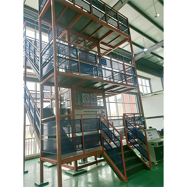
2. Equipment size: 4500×4500×8000mm (length×width×height);
3. Elevator shaft size: 1800×1900mm (width×depth);
4. Car net size: 1100×1100×1480mm (width×depth×height);
3. Net door opening size: 650×1200mm (width×height);
4. Lifting height: 2700mm;
5. Rated speed: 0.3m/s;
6. Center opening door type;
7. Collective frequency conversion control mode;
8. Safety protection measures: grounding protection, overcurrent, overload, leakage protection and anti-fall and anti-collision protection functions, in line with national elevator standards.
9. Maximum power consumption ≤5.5KW.
Fire protection function: automatic return to base station in case of fire alarm;
Leveling accuracy: ±3MM;
External call design: Floor: high-quality textured st*nless steel panel, light-touch button, red dot matrix digital display of floor station;
Control system: PLC microcomputer control;
Traction system: AC variable frequency voltage and speed regulation (VVVF);
Traction machine type: permanent magnet synchronous;
Door machine type: variable frequency door machine;
Door protection system: full-optical antenna protection system;
Car ventilation: cross-flow fan;
Safety protection measures: grounding protection, overcurrent, overload, leakage protection and anti-fall, anti-collision protection functions, in line with relevant national standards.
1. System Overview: The opening and closing of the elevator door is realized by the door blade installed on the car door. Each door is equipped with a door lock. After the door is closed, the mechanical lock hook of the door lock is engaged, and the elevator can start to run. In order to reflect the authenticity of the equipment as much as possible, the simulated hoistway of the steel structure support, the real elevator mechanism and components simulate the real working environment of the elevator.
The traction system is m*nly composed of the traction machine, traction wire rope, guide wheel, anti-rope wheel, etc. The traction machine is composed of a permanent magnet synchronous motor, a brake, etc., which provides power for the operation of the elevator. The wire rope connects the car and the counterweight to drive the car up and down. The traction machine is located on the top of the cabinet frame and is the power device of the elevator. It is installed on two load-bearing beams and is m*nly composed of the following parts: The motor is a squirrel cage three-phase induction motor, which adopts the variable frequency (VVVF) drive mode. When the elevator starts, the frequency converter makes the stator current frequency start from a very low frequency and rise to the rated frequency according to the control requirements. When decelerating, the speed is correspondingly smoothly reduced from the rated frequency to zero, achieving elevator leveling, ensuring the smooth operation of the elevator, and truly simulating the good fit of the elevator.
2. Guide system: m*nly composed of guide r*ls, guide shoes, guide r*l brackets, etc.; guide shoes are installed on the car and counterweight frame, and cooperate with the guide r*ls to force the car and counterweight to move on the guide r*ls; the guide r*l frame m*nly supports the guide r*ls.
3. Car system: It consists of the car frame and the car body (car wall, car top, car bottom and control box, etc.). The car is suspended by traction wire ropes and connected to the counterweight through the other end of the traction machine. It runs on the guide r*ls. The car is equipped with automation, and the door is equipped with a ch*n switch. The elevator can only run when the door is closed. There is also a safety touch panel on the door. When an obstacle is encountered during the door closing process, the car door will open immediately.
4. Safety and door lock circuit: It consists of relay circuits. The emergency stop and the on and off of the door lock switch determine whether the safety and door lock circuits are normal or not, so that the PLC can determine whether the elevator is in a safe state. The system consists of car doors, floor doors, door openers, door lock devices, etc.
5. Overspeed safety protection system: When an accident occurs in the elevator, the car will overspeed or slide down at high speed (such as wire rope breakage, car top pulley detachment, traction machine f*lure, motor speed reduction too high, etc.). At this time, the speed limiter will brake urgently, and drive the safety clamp to operate through the safety steel cable and connecting rod mechanism, so that the car is stuck on the guide r*l and will not fall.
6. Weight balance system: It is composed of counterweight and counterweight block devices.
7. Spring buffer system for car and counterweight: The buffer is a safety device for the extreme position of the elevator. When the elevator f*ls and causes the car or counterweight to squat or hit the top (the limit switch protection f*ls), the car or counterweight hits the spring buffer, and the buffer absorbs the energy of the elevator, so that the car or counterweight can be safely decelerated until it stops.
8. Electric traction system: It is composed of power supply system, traction motor, speed feedback device, speed control device, etc.; it m*nly provides power to realize elevator speed control.
9. Electrical control system: It is composed of operating device, position display device, control cabinet, leveling device, floor selector, etc. Operating box: It is located on the left side of the front of the cabinet frame, and is a signal input device that simulates the passenger's floor selection in the car, including a large-screen high-definition LCD display that can display the location of the car floor; "1", "2", "3" floor selection buttons; door opening and closing buttons: direction indicator lights, used to indicate the direction of elevator operation; power lock, control the power of the elevator, that is, the first floor external call box.
11. Programmable controller: It controls the running status of the elevator, makes logical judgments on the position of the elevator according to the call signal, and then gives running instructions to enable the elevator to realize functions such as answering the call signal and automatically closing the door.
12. Safety protection system: It is m*nly composed of speed limiter, safety clamp, buffer, terminal protection device, etc. It ensures the safe use of the elevator and prevents all accidents.
13. Terminal protection switch: The sensor provides the elevator operation terminal signal. When the elevator exceeds it, the safety circuit and power supply are cut off to ensure that the elevator does not exceed the terminal.
14. Comprehensive integrated tr*ning virtual simulation system for professional skills The model
in the software can be rotated 360°, enlarged, reduced, and translated. There are universal interactive buttons: return, home page, help. There are prompts for all virtual simulation task processes, and the software automatically checks after completing a task. There are experimental tasks above the tool library
1. Basic solid ( the XYZ space coordinate icon automatically rotates with the model
when it is rotated.) A. Plane solid: The experimental steps are divided into experimental tasks (text prompt tasks) - build model (drag the model in the tool library to the three-projection surface system, and the projection will be automatically displayed. There will be prompts when the selection is wrong) - change posture (change by clicking the up, down, left, and right arrows) - select projection (enter the answering interface, and select the three-dimensional projection diagram completed at this time from the 6 items)
B. Cut solid: The experimental steps are divided into experimental tasks (text prompt tasks) - build model (drag the model in the tool library to the three-projection surface system, and the projection will be automatically displayed) - mark the projection situation (mark the three-dimensional projection diagram, and select the corresponding annotation symbol in the 14 blank columns)
C. Intersecting solids: The experimental steps are divided into experimental tasks (text prompt tasks) - digging holes (select any digging hole model, then you can select any surface in the XYZ space coordinates, the models will switch at the same time, and a coordinate slider will appear. According to the displacement of the slider, the model will have a corresponding degree of cross-section) - aperture change (select 1-4 apertures) - rear through hole - select projection (enter the answering interface, and select the completed three-dimensional projection diagram at this time in 8 items)
2. Assembly
A. Assembly assembly: The experimental steps are divided into experimental tasks (text prompt tasks) - select the assembly model (8 models can be selected) - assemble the assembly (select the tool library model according to the selected model and drag and drop the assembly) - section the assembly (you can select any surface in the XYZ space coordinates, the models will switch at the same time, and a coordinate slider will appear. According to the displacement of the slider, the model will have a corresponding degree of cross-section) - select side projection (enter the answering interface, based on the known front and horizontal projection diagrams, select the correct side projection diagram in 3 items)
B. Assembly drawing reading: The experimental steps are divided into experimental tasks (text prompt tasks) - select the assembly section view (8 types of drawings can be selected) - build the assembly model (select the tool library model according to the selected model and drag and drop the combination) - cut the assembly (you can select any surface in the XYZ space coordinates, the model will switch at the same time, and a coordinate slider will appear. According to the displacement of the slider, the model will appear with a corresponding degree of section) - select the left view (enter the answer interface, according to the known m*n view and top view, select the correct left view from the 3 items)
3. Assembly
A. Mechanical transmission mechanism : 8 mechanisms (worm gear, gear rack, spiral transmission, plane external meshing gear, plane internal meshing gear, space spur bevel gear, belt drive , ch*n drive) are optional. After selecting, the model will appear in the toolbar. Drag the model freely to combine. After the combination is completed, the model can be operated. Each mechanism comes with an introduction, video demonstration, and drawing method. There are 6 questions in the answer interface, and each question has 4 options.
B. Gear oil pump: Select the tool library model according to the prompts and build the model step by step. You can choose to learn the introduction, drawing method, and animation principle (the internal movement principle of the model can be visualized). There are 2 questions in the answering interface, and each question has 4 options.
C. Mechanical mechanism construction: 2 mechanisms (2-DOF robotic arm, 3-DOF robotic arm). Select the tool library model according to the prompts and build the model step by step. After the combination is completed, the model can be operated. Each mechanism has an introduction and video demonstration. There are 2 questions in the answering interface (both models must be built before entering), and each question has 4 options.
15. Tr*ning contents that need to be completed:
1). Tr*ning on detection, adjustment and fault finding of traction motor variable frequency drive control circuit;
2). Tr*ning on mechanical adjustment and fault finding of traction machine brake;
3). Tr*ning on detection, adjustment and fault finding of car door motor variable frequency drive control circuit;
4). Tr*ning on speed limiter action adjustment;
5). Tr*ning on detection and fault finding of speed limiter action control circuit;
6). Tr*ning on detection, adjustment and adjustment of safety clamp;
7). Tr*ning on detection, adjustment and adjustment of safety clamp transmission mechanism;
8). Tr*ning on adjustment, m*ntenance, fault finding and troubleshooting of car door transmission mechanism;
9). Tr*ning on fault finding and troubleshooting of car door control circuit;
10). Tr*ning on adjustment, m*ntenance, fault finding and troubleshooting of hall door transmission mechanism;
11). Tr*ning on fault finding and troubleshooting of hall door control circuit;
12). Tr*ning on detection and adjustment of car guide r*l;
13). Tr*ning on detection and adjustment of counterweight guide r*l;
14). Tr*ning on detection and adjustment of guide shoe and guide r*l;
15). Leveling device adjustment and control circuit fault finding and troubleshooting tr*ning;
16). Floor car call box adjustment and control circuit fault finding and troubleshooting tr*ning;
17). Car button control box control circuit fault finding and troubleshooting tr*ning;
18). Floor indicator light box control circuit fault finding and troubleshooting tr*ning;
19). Car top inspection box control circuit fault finding and troubleshooting tr*ning;
20). Upper limit position protection device control circuit fault finding and troubleshooting tr*ning;
21). Lower limit position protection device control circuit fault finding and troubleshooting tr*ning;
22). Lighting control circuit fault finding and troubleshooting tr*ning;
23). Communication circuit fault finding and troubleshooting tr*ning;
24). Microcomputer control circuit fault finding and troubleshooting tr*ning;
25). Power supply circuit fault finding and troubleshooting tr*ning;
18. Faults that need to be eliminated:
Fault 1: GU (324-310) upper forced deceleration sensor is damaged, the elevator cannot go up normally, but can go down.
Fault 2: GD (325-310) lower forced deceleration sensor is damaged, the elevator cannot go down normally, but can go up.
Fault 3: SW (264-310) upper limit sensor is damaged, the elevator cannot go up normally, but can go down.
Fault 4: XW (265-310) lower limit sensor is damaged, the elevator cannot go down normally, but can go up.
2. Contact, switch, button f*lure:
Fault 5: KAB (268-310) touch panel switch f*lure, safety touch panel invalid
Fault 6~7: AK (268-310); AG (269-310) door opening and closing buttons f*lure, can not open and close the door.
Fault 8~12: 1AS (1A-310); 2AS (2A-310); 3AS (3A-310); 4AS (4A-310); 5AS (5A-310) internal selection button f*lure, the selected floor button signal cannot be registered.
Fault 13~16: 1SA (1S-310); 2SA (2S-310); 3SA (3S-310); 4SA (4S-310) The selected floor button signal cannot be registered, and the up call button f*ls.
Faults 17~20: 2XA (2X-310); 3XA (3X-310); 4XA (4X-310); 5XA (5X-310) The down call button f*ls, and the selected floor button signal cannot be registered.
Faults 21~22: PKM (237-301); PGM (243-301) The door is in place, the switch is damaged and cannot be closed, causing the door opening or closing relay to f*l to energize.
Faults 23~27: TS1 (1T1、2T1); TS2 (1T2、2T2); TS3 (1T3、2T3); TS4 (1T4、2T4); TS5 (1T5、2T5) Hall door interlock switch circuit fault, the elevator cannot operate.
Fault 28: SQF (PGM) (111、301) Door closing f*lure, the elevator cannot operate. Faults
29~31: SJN (301、131); SAQ (129、127); SDS (125、123) Safety circuit, electrical circuit fault, the elevator cannot operate.
Faults 32~33: KDX (115~113); JR (113~101) Phase sequence, thermal relay fault, the elevator cannot operate.
Fault 34: DYJ (261-310) Safety circuit relay contact is poor, the elevator cannot perform any operation.
Fault 35: MSJ (262-310) The relay contacts of the door interlock circuit are in poor contact, the elevator cannot run but the door can be opened and closed.
Faults 36~37: KMJ (582-301); KMJ (304-482) The contacts of the door opening relay in the door opening circuit are in poor contact, resulting in a lack of power to the door motor and the inability to open the door.
Faults 38~39: GMJ (482-301); GMJ (304-682) The contacts of the door closing relay in the door closing circuit are in poor contact, resulting in a lack of power to the door motor and the inability to close the door.
Faults 40~41: KMJ (241-244); GMJ (235-239) The normally closed contacts of the door opening relay in the door opening relay circuit are in poor contact, resulting in the inability of the door opening relay or the door closing relay to be attracted.
3. PLC output relay f*lure:
Fault 42~46: Y10 (1R-304); Y11 (2R-304); Y12 (3R-304); Y13 (4R-304); Y14 (5R-304) The internal selection button light and output button light are not on.
Fault 47~48: Y6 (11, J6); Y7 (11, J7) PLC output f*lure causes the inverter to malfunction or f*l to operate.
A: Each fault point is set outside the switch.
B: Each fault point is led to the fault terminal block.
C: Each fault switch is connected in series.
| Serial number | name | M*n Specifications | quantity | unit | Remark |
| 1 | Well and observation platform |
5000×4500×8000 (length×width×height) mm |
1 | set | |
| 2 | Traction machine | 1 | set | Permanent magnet synchronous motor | |
| 3 | Car guide r*ls | 1 | set | ||
| 4 | Counterweight guide r*l | 1 | set | ||
| 5 | Car frame | 1 | set | ||
| 6 | Car | 1 | set | ||
| 7 | Speed governor-tensioner | 1 | set | ||
| 8 | Speed governor transmission wire rope | 1 | set | ||
| 9 | Traction wire rope | 1 | set | ||
| 10 | Safety Gear | 1 | set | ||
| 11 | Safety gear transmission mechanism | 1 | set | ||
| 12 | Floor greeting box | 2 | set | ||
| 13 | Layer light box | 2 | set | ||
| 14 | Car operation box | 1 | set | ||
| 15 | Upper limit protection device | 1 | set | ||
| 16 | Lower limit protection device | 1 | set | ||
| 17 | Leveling control device | 2 | set | ||
| 18 | M*n control cabinet | 1 | set | ||
| 19 | Car roof m*ntenance box | 1 | set | ||
| 20 | Elevator lighting | 1 | set | ||
| twenty one | Tr*ning guide | Tr*ning Guide for Elevator Installation, Rep*r and M*ntenance Tr*ning and Assessment Device | 1 | Book | |
| twenty two | Tr*ning tools | 1 | set | See Appendix 1 for det*ls |
| Serial number | name | Model/Specification | quantity | unit | Remark |
| 1 | helmet | 2 | indivual | ||
| 2 | seat belt | Double back safety belt | 2 | set | |
| 3 | Isolation belt | Cordon fence | 2 | root | |
| 4 | Safety warning signs | Rep*r bracket sign | 1 | indivual | |
| 5 | Danger Bracket Sign | 1 | indivual | ||
| 6 | Listing | M*ntenance sign | 1 | indivual | |
| 7 | Level | 600mm | 1 | Bundle | |
| 8 | Fall line | Magnetic | 1 | branch | |
| 9 | Steel ruler | 300mm | 1 | Item | |
| 10 | hammer | 3 lbs | 1 | Bundle | |
| 11 | adjustable wrench | 250×30 | 1 | Bundle | |
| 12 | 300×36 | 1 | Bundle | ||
| 13 | Flathead screwdriver | 3` | 1 | Bundle | |
| 14 | 3×75 | 1 | Bundle | ||
| 15 | Phillips screwdriver | 3` | 1 | Bundle | |
| 16 | 3×75 | 1 | Bundle | ||
| 17 | multimeter | Huayi MY60 | 1 | Item | |
| 18 | Electric pen | Deli 8001 | 1 | branch | |
| 19 | Rasp | Flat file 8 inches | 1 | branch | |
| 20 | Flat file 6 inches | 1 | branch | ||
| twenty one | tape measure | 3m | 1 | Bundle | |
| twenty two | Marker pen | 1 | branch | ||
| twenty three | Insulation tape | 1 | roll | ||
| twenty four | Needle Nose Pliers | 6 inches | 1 | Bundle | |
| 25 | Diagonal pliers | 6 inches | 1 | Bundle | |
| 26 | Hexagon wrench | 10-piece set | 1 | set | |
| 27 | Open-end wrench | 8-10 | 1 | Bundle | |
| 28 | 10-12 | 1 | Bundle | ||
| 29 | 13-16 | 1 | Bundle | ||
| 30 | 14-17 | 1 | Bundle | ||
| 31 | 18-21 | 1 | Bundle | ||
| 32 | 19-22 | 1 | Bundle | ||
| 33 | 24-27 | 1 | Bundle | ||
| 34 | Wrenches | 8-10 | 1 | Bundle | |
| 35 | 13-16 | 1 | Bundle | ||
| 36 | 14-17 | 1 | Bundle | ||
| 37 | 18-21 | 1 | Bundle | ||
| 38 | 19-22 | 1 | Bundle | ||
| 39 | 24-27 | 1 | Bundle | ||
| 40 | Calibration Ruler | JS-302 | 1 | pay | |
| 41 | Clamp ammeter | MS2026 | 1 | Item | |
| 42 | Door lifter | 1 | Item | ||
| 43 | Feeler gauge | 1 | Bundle | ||
| 44 | Toolbox | 2 | branch | ||
| 45 | Triangle key | 1 | Bundle | ||
| 46 | padlock | 1 | Only | ||
| 47 | Elevator lock key | 1 | Bundle |
 Wechat scan code follow us

24-hour hotline+86 18916464525

Phone18916464525
ADD:Factory 414, District A, No. 6, Chongnan Road, Songjiang Science and Technology Park, Shanghai ICP: Sitemap