DYLR-DL air conditioning system multi-connection system training platform
Release time:2024-06-17 12:57viewed:times
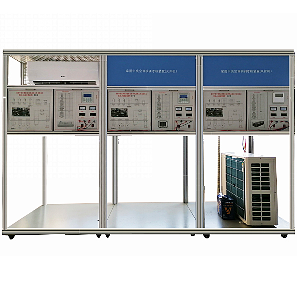
1. Product Overview The
variable refrigerant volume (VRV) *r conditioning system is a high-efficiency refrigerant *r conditioning system that uses variable frequency compressors, electronic expansion valves and advanced control systems to control the refrigerant circulation volume of the compressor and the refrigerant flow entering the indoor heat exchanger in the electric *r conditioning system to meet the indoor cooling and heating load requirements in real time. VRV *r conditioning systems have many advantages such as energy saving, comfort, stable operation, and relatively small building space occupation. They can better meet the personalized use requirements of users and are widely used in buildings ranging from several hundred to twenty thousand square meters.
2. M*n features
1. The system uses VRV units, which are characterized by excellent quality, small size, and variable frequency adjustment of the compressor. The adjustable range of the variable frequency compressor is between 48% and 104% of its rated capacity. Its energy adjustment must take into account the time required for the compressor frequency adjustment. Due to the dynamic characteristics of the variable frequency compressor itself, the energy should be less than a cert*n speed when adjusting the energy, so the adjustment is step-by-step and stage-by-stage adjustment; and the speed of the compressor motor changes proportionally according to the indoor *r conditioning load.
2. Diversification of system terminal processors: Let students understand the diverse structural forms of indoor units. Each terminal processor is equipped with a refrigeration system flow board, a control circuit flow board, a temperature gauge and a pressure gauge, and all control circuits of the unit can be observed.
3. System integrity and independence: The control function, protection function and display function are completely consistent with those of actual household central *r conditioners, and each user terminal can be independently controlled under the same working conditions.
The operating table only needs an AC 220V power supply to be put into use, which occupies a small area, saves room and reduces infrastructure investment.
4. The device intuitively displays the system structure and working principle of household central *r conditioners, which is convenient for teachers to demonstrate and expl*n and for students to understand and master textbook knowledge. Reasonable structure and beautiful shape The device has a reasonable and compact structure and beautiful shape. The tr*ning table is also equipped with four universal wheels and four fixed adjustment mechanisms for easy movement and fixation.
The tr*ning device system is equipped with a simulated fault setting function to set faults in the refrigeration system and electrical system. Improving students' analytical ability through specific phenomena is conducive to students applying theory to practice and cultivating their practical hands-on ability.
5. It is equipped with a current-type leakage protection device. When the ground leakage current exceeds a cert*n value, the circuit breaker will trip and cut off the power supply; and there are thermal protection devices to protect the compressor from overheating and overload.
4. Technical parameters
1. Power supply: three-phase five-wire AC380V±10% 50Hz outdoor unit total current 25A
2. Working environment: temperature -10℃~+40℃ relative humidity ≤85% altitude ≤4000m
3. Microcomputer frequency conversion control is adopted, and centralized control and m*ntenance can be achieved through the bus.
4. With a dedicated data acquisition system, the host computer can realize parameter detection, fault recording, data curves, etc.
IV. System composition
VRV *r-conditioning outdoor unit, various types of indoor units, fresh *r ventilator, refrigerant pipe, branch, condensate pipe, *r supply pipe, *r outlet, outdoor unit controller, indoor unit controller, centralized controller, host computer m*ntenance workstation, communication converter, power distribution system
V. Tr*ning projects
[I] Junior worker tr*ning:
1. VRV *r-conditioning system cognition and operation 2. Basic knowledge of electrical control principle of outdoor unit
3. Basic knowledge of electrical control principle of indoor unit (three types of indoor units) 4. Refrigeration system process
5. System operation under different working conditions 6. System fault simulation setting
[II] Intermediate worker tr*ning:
1. Central *r-conditioning system installation and commissioning 2. Central *r-conditioning system installation
3. Central *r-conditioning control system installation 4. Central *r-conditioning engineering commissioning
5. Installation methods and standards of outdoor units and indoor units 6. Installation methods and standards of piping systems
7. Installation methods and standards of power distribution and control systems 8 M*n contents, steps and methods of engineering commissioning
9. Common problems of refrigeration system 10. Common problems in power distribution system
11. Common problems in control system 12. Use of data acquisition system, data analysis and diagnosis
13. Refrigeration performance test 14. Experimental study on operating parameters, energy consumption, energy efficiency ratio, and factors affecting energy efficiency ratio and energy consumption
15. Experiment II: Heating performance test (heat pump)
[III] Electrical assessment tr*ning:
1. Conventional fault diagnosis and analysis 2. Microcomputer fault diagnosis and analysis
3. High-voltage protection tr*ning 4. Indoor sensor tr*ning
5. Communication circuit tr*ning 6. Indoor unit three communication fault
7. Indoor unit two communication fault 8. Indoor unit one communication fault
9. Indoor two sensor tr*ning 10. Indoor three sensor tr*ning
11. Indoor unit installation and setting tr*ning 12. Control panel fault analysis
13. Analysis of the phenomenon of reducing indoor unit
★ Intelligent multi-connection test control software
1. Central *r conditioning test
program Central *r conditioners are complex and have scattered equipment. Some have already been installed with test programs on the ceiling. Once a fault occurs, the amount of work is quite large. In order to quickly and accurately determine whether the fault is caused by the host unit or the indoor unit, each manufacturer has developed a central *r conditioner test program based on production and m*ntenance needs. It can test the operating frequency of the compressor, various data of the sensor, the working steps of the electronic expansion valve and dozens of other central *r conditioner working data and states. The software can control the indoor units and set the states of 1-64 indoor units. It is a good research and learning device for colleges and universities.
Central *r conditioning test and m*ntenance control program software; can accurately and quickly determine which unit the fault occurred in. The software also displays more than 100 online data and operating status of the *r conditioner. Different models have different interfaces, specifically: 1 to 16 (EVI), 1 to 32, digital modular 1 to 64, variable frequency modular 1 to 64, heat recovery, single-machine DC variable frequency, single-machine AC variable frequency, intelligent variable frequency, single-machine 420, single-machine 900, modular *r-cooled screw and other central *r conditioners.
Single-chip microcomputer , PLC programmable design and control virtual simulation software:
This software is developed based on unity3d, with built-in experimental steps, experimental instructions, circuit diagrams, component lists, connection lines, power on, circuit diagrams, scene reset, return and other buttons. After the connection and code are correct, the three-dimensional machine tool model can be operated through the start/stop, forward motion, and reverse motion buttons . When the line is connected, the three-dimensional machine tool model can be enlarged/reduced and translated.
1. Relay control: Read the experimental instructions and enter the experiment. By reading the circuit diagram, select relays, thermal relays, switches and other components in the component list and drag and drop them into the electrical cabinet. The limiter is placed on the three-dimensional machine tool model. You can choose to cover the cover. Some component names can be renamed. Then click the connect line button to connect the terminals. After the machine tool circuit is successfully connected, choose to turn on the power and operate. If the component or line connection is wrong, an error box will pop up. The scene can be reset at any time.
2. PLC control: The experiment is the same as relay control, and the PLC control function is added. After the connection is completed, enter the program writing interface through the PLC coding button. Write two forward and reverse programs. There are 12 ladder diagram symbols in total. After writing, select Submit for program verification. After successful verification, turn on the power to operate. If there are component, line connection, and code errors, an error box will pop up. The scene can be reset at any time.
3. Single-chip microcomputer control: The experiment is the same as relay control, with the addition of single-chip microcomputer control function. After the connection is completed, enter the programming interface through the C coding button, enter the correct C language code, submit and verify successfully, turn on the power to operate, and a prompt error box will pop up for component, line connection, and code errors, and the scene can be reset at any time.


 Wechat scan code follow us
