DYLR-2017J Intelligent Refrigeration Compressor Performance Test Training Platform
Release time:2024-06-17 11:30viewed:times
1. Product Overview The
"Intelligent Refrigeration Compressor Performance Test Tr*ning Device" uses a programmable controller PLC as the control core, and is based on the national standard GB/T5773-2004 "Positive Displacement Refrigeration Compressor Performance Test Method", with the second refrigerant calorimeter method as the m*n measurement method and the water-cooled condenser method as the auxiliary measurement method. There are two modes for test condition adjustment, test data collection and test data processing: manual and automatic. It is suitable for teaching and tr*ning of refrigeration-related courses in various colleges and universities.
II. System Features
1. It consists of two systems, one is the compressor test system, and the other is the subcooling adjustment auxiliary system
2. The stability of the system working condition is controlled by PID control algorithm and intelligent control algorithm with prediction mechanism
III. Technical Performance
1. Input power: three-phase four-wire ~ 380V±10% 50Hz
2. Working environment: temperature -10℃~+40℃ Relative humidity <85%(25℃) Altitude <4000m
3. Device capacity: <5k VA
4. Refrigerant: R22
5. Second refrigerant: R123
6. Cooling capacity: 2.3kW
7. Weight: 100kg
8. It is equipped with voltage leakage protection, current leakage protection, overcurrent protection, overload protection and grounding protection, and its safety meets the relevant national standards.
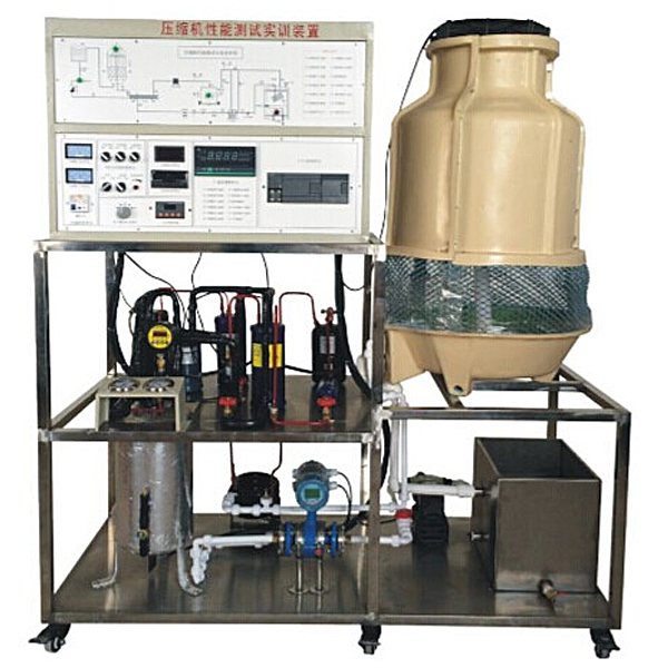
IV. Configuration and technical performance The tr*ning device is m*nly composed
of a control console, a compressor test system, a subcooling adjustment auxiliary system, a host tr*ning module, a temperature acquisition module, a pressure transmitter and a flow sensor
. 1. Control console
(1) The AC power
supply provides the three-phase AC power required for the control panel to work, which can be controlled by the m*n power switch. It is equipped with three pointer-type AC voltmeters, which respectively indicate the input three-phase grid voltage value.
(2) The safety protection system
is equipped with voltage-type leakage protection, current-type leakage protection, overcurrent protection, overload protection, and grounding protection, which can effectively protect people and equipment.
(3) Tr*ning table
The tr*ning table is an iron double-layer matte dense-gr*ned spray-coated structure. The desktop is a fireproof, waterproof, wear-resistant high-density board with a solid structure and beautiful appearance. It is equipped with two large drawers for placing tools and materials. The desktop is used to install the power control panel and provides a spacious and comfortable work surface. The tr*ning table is also equipped with four universal wheels for easy movement and fixing.
2. The compressor test system
includes the tested compressor, horizontal shell and tube condenser, cooling tower, condensate circulating water pump, sight glass, filter dryer, electronic expansion valve, water flow regulating valve, liquid receiver and calorimeter, etc.
3. The subcooling adjustment auxiliary system
consists of subcooler, circulating water pump, water flow regulating valve, cooling tower, etc.
4. Measuring instruments
(1) Pointer voltmeter: range 0~450V
(2) Vacuum pressure gauge: range -0.1~1.5MPa
(3) Vacuum pressure gauge: range -0.1~3.5MPa
(4) Digital temperature meter: using PT100 sensor, measuring range -50~+150℃
(5) Glass rotor flowmeter: range 16~160mL/min
(6) Power meter: accuracy 0.5, can display voltage, current and power signals separately
5. The host tr*ning module
is equipped with Siemens CPU224 PLC (AC/DC/RLY) host, integrated digital I/O (14 digital inputs/10 digital outputs), with 1 RS-485 communication port, and supporting PC/PPI programming cable.
6. The temperature acquisition module
is equipped with Siemens EM231 analog module (4 analog inputs) and EM232 analog module (2 analog outputs).
7. The detection sensor
includes pressure transmitter and flow sensor.
8. Single chip microcomputer , PLC programmable design and control virtual simulation software:
This software is developed based on unity3d, with built-in experimental steps, experimental instructions, circuit diagram, component list, connection line, power on, circuit diagram, scene reset, return and other buttons. After the connection and code are correct, the three-dimensional machine tool model can be operated by the start/stop, forward movement, and reverse movement buttons . In the state of connecting the line, the three-dimensional machine tool model can be enlarged/reduced and translated.
1. Relay control: Read the experimental instructions and enter the experiment. By reading the circuit diagram, select the relay, thermal relay, switch and other components in the component list and drag and drop them to the electrical cabinet. The limiter is placed on the three-dimensional machine tool model. You can choose to cover the cover. Some component names can be renamed. Then click the connection line button to connect the terminal to the terminal. After the machine tool circuit is successfully connected, choose to turn on the power and operate. If the component or line connection is wrong, an error box will pop up, and the scene can be reset at any time.
2.PLC control: The experiment is the same as relay control, with the addition of PLC control function. After the connection is completed, enter the program writing interface through the PLC coding button, write two programs, forward and reverse, with a total of 12 ladder diagram symbols. After the writing is completed, select Submit to verify the program. After the verification is successful, turn on the power to operate. Errors in components, line connections, and code will pop up prompt error boxes, and the scene can be reset at any time.
3. Single-chip microcomputer control: The experiment is the same as relay control, with the addition of single-chip microcomputer control function. After the connection is completed, enter the programming interface through the C coding button, enter the correct C language code, and submit the verification successfully. Turn on the power to operate. Errors in components, line connections, and code will pop up prompt error boxes, and the scene can be reset at any time.
V. Practical tr*ning projects
1. Understand the practical tr*ning methods of the national standard GB/T5773-2004
2. The basic structure and working principle of the vapor compression refrigeration cycle system
3. Test condition control of the compressor test system
4. Relative error measurement of the m*n and auxiliary cooling capacity
5. Energy efficiency ratio measurement of the refrigeration unit


 Wechat scan code follow us
