Shanghai Daiyu Education Equipment Manufacturing Co., Ltd.
Language:


| serial number | name | Specifications and models | unit | quantity |
| 1 | Lithium iron phosphate power battery pack | Original car | set | 1 |
| 2 | Battery Management System (BMS) | Original car | set | 1 |
| 3 | BMS display (instrument) | Original car | set | 1 |
| 4 | M*ntenance switch | Original car | set | 1 |
| 5 | Auxiliary battery | 12V60AH | Only | 1 |
| 6 | Charging piles and charging guns | Vehicle package | set | 1 |
| 7 | High voltage cable | Original car | set | 1 |
| 8 | High voltage distribution box | Original car | set | 1 |
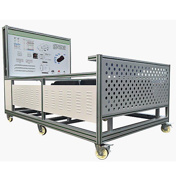
| 9 | Movable platform and teaching board with table top/mobile stand (with self-locking casters) |
1740×600×1700mm (length×width×height); 1200*700*800mm(length×width×height); |
set | 1 |
| 10 | Test control panel |
Equipped with various detection terminals as well as color circuit diagrams and working principle diagrams (panel: 1700*900*4mm) |
set | 1 |
 Wechat scan code follow us

24-hour hotline+86 18916464525

Phone18916464525
ADD:Factory 414, District A, No. 6, Chongnan Road, Songjiang Science and Technology Park, Shanghai ICP: Sitemap