Shanghai Daiyu Education Equipment Manufacturing Co., Ltd.
Language:


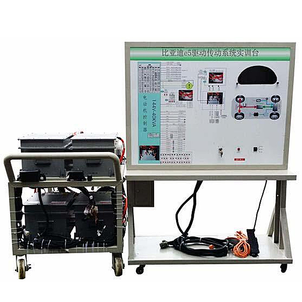


| serial number | name | Specifications and models | unit | quantity |
| 1 | High voltage electronic control assembly | Original car | set | 1 |
| 2 | M*n controller assembly (motor controller, etc.) | Original car | set | 1 |
| 3 | gateway controller | Original car | set | 1 |
| 4 | Fast charging interface | Original car | set | 1 |
| 5 | Slow charging interface | Original car | Only | 1 |
| 6 | P gear controller | Original car | set | 1 |
| 7 | Brake pedal assembly | Original car | set | 1 |
| 8 | electronic accelerator pedal | Original car | set | 1 |
| 9 | Permanent magnet synchronous motor with sensor accessory assembly | Original car | set | 1 |
| 10 | Motor cooling system | Original car | set | 1 |
| 11 | Gearbox assembly | Original car | set | 1 |
| 12 | Drive shaft assembly | Original car | set | 2 |
| 13 | Brake disc assembly | Original car | set | 2 |
| 14 | DC-DC module | Original car | set | 1 |
| 15 | Movable platform and teaching board with table top/mobile stand (with self-locking casters) | 1740×600×1700mm (length×width×height); | set | 1 |
| 16 | Test control panel |
Equipped with various detection terminals as well as color circuit diagrams and working principle diagrams (panel: 1700*900*4mm) |
set | 1 |
 Wechat scan code follow us

24-hour hotline+86 18916464525

Phone18916464525
ADD:Factory 414, District A, No. 6, Chongnan Road, Songjiang Science and Technology Park, Shanghai ICP: Sitemap