dyxnydp-06 New Energy Vehicle ABS Anti-Holding Brake System Experimental Device
Release time:2024-05-26 10:00viewed:times
1. Product Introduction
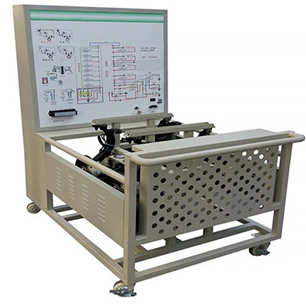
This equipment is based on the ABS/EBD braking system of BAIC EV160 new energy vehicle . It is equipped with a working principle diagram of the ABS system to truly demonstrate the working process of the ABS/EBD system during emergency braking.
It meets the teaching functions of the structure, composition, action demonstration and other functions of the ABS/EBD braking system.
It is suitable for the teaching needs of theoretical teaching and testing and m*ntenance tr*ning of automotive ABS/EBD braking systems.
2. Functional features
1. Based on the real car ABS/EBD braking system, it fully displays the structure of the ABS braking system.
2. The three-phase asynchronous motor drives the front and rear axles to rotate to simulate car driving. When the brake pedal is pressed in an emergency, the ABS/EBD system starts to work, the front and rear brake discs keep rotating slightly, and you can feel a constant bounce on the brake pedal, truly demonstrating the working process of the car's ABS/EBD system.
3. There are color UV flat panel printed circuit diagrams and hydraulic pipeline diagrams on the tr*ning platform . Tr*nees can visually compare the circuit diagrams with the actual ABS braking system to understand and analyze the working principle of the control system. 4. There are detection terminals installed on the panel of the tr*ning platform, which can directly detect the electrical signals of each sensor and control unit pins on the panel , such as resistance, voltage, current, frequency signals, etc. 5. The tr*ning platform is equipped with a pressure gauge, which can display the hydraulic changes of the brake master cylinder and four brake cylinders in real time. 6. A fault indicator light and a diagnostic socket are installed on the tr*ning bench panel, which can be connected to a special or general vehicle decoder to perform ECU code query, read fault codes, clear fault codes, and read data streams for the ABS/EBD electronic control system. , actuator testing, parameter setting, waveform analysis and other self-diagnostic functions. 7. Equipment panel cabinet: 1.5mm cold plate stamping and forming, with a m*ntenance door on the back; the base is welded with a steel structure, the surface is spray-coated, and has a self-locking caster device, which makes it flexible to move, safe, reliable, sturdy and durable. 8. Mechanical assembly and fitter assembly virtual simulation software: This software is developed based on unity3d, with optional 6-level image quality. It is equipped with the design and virtual disassembly and assembly of reducers and shafting structures, the design and simulation of common mechanical mechanisms , and a mechanism resource library. For a typical mechanical mechanism (virtual disassembly and assembly of a gasoline engine), the software is a whole software and cannot be individual resources. A. Reducer design and virtual disassembly interface can choose worm gear bevel gear reducer, two-stage expanded cylindrical gear reducer, bevel cylindrical gear reducer, coaxial cylindrical gear reducer, bevel gear reducer, and one-stage cylindrical gear reducer. Gear reducer. Worm bevel gear reducer: After entering the software, the assembly content is automatically played. Each step in the video has a text description . Secondary expandable cylindrical gear reducer: After entering the software, the content is played in the form of a video. The video content should include: Part name ( Scan the QR code to see the names of parts), disassembly and assembly demonstration (including disassembly and assembly), virtual disassembly (including overall, low-speed shaft, medium-speed shaft, high-speed shaft, box cover, box seat) conical cylindrical gear reducer, Coaxial cylindrical gear reducer, bevel gear reducer, first-level cylindrical gear reducer: click to enter and automatically jump to the edrawings interface. The models are all three-dimensional models . By clicking on the parts, the names of the parts are displayed, and the 360° view is av*lable Rotate, enlarge, reduce, translate, and at the same time, the entire reducer can be disassembled and assembled through the moving parts function. At the same time, you can select the home button to return to the original state of the reducer. The bevel gear reducer and first-stage cylindrical gear reducer have added the function of inserting a cross section, and the cross section can be freely dragged to observe the internal structure of the reducer. B. Shaft structure design and virtual disassembly and assembly interface optional parts recognition, disassembly and assembly demonstration, and actual operation. 1. Parts recognition: three-dimensional model and part name including helical gear, non-hole end cover, coupling, coupling key, shaft, gear key, hole end cover, shaft sleeve, deep groove ball bearing, any All parts can be rotated 360° 2. Disassembly and assembly demonstration: There are 2 built-in cases. When you move the mouse to the position of a cert*n part (except the base and bearing seat), the part will automatically enlarge and the name of the part will be displayed. It is equipped with disassembly and Assembly button, the function is to automatically complete the disassembly and assembly of the shaft system structure by the software. All three-dimensional scenes can be rotated, enlarged, reduced and translated 360° in all directions. 3. Practical operation: The three-dimensional parts are neatly placed on the table. Students manually select the corresponding parts and move them to the shaft system structure. The parts can be installed only when they are placed in the correct order and in the correct position. There is a restart button to facilitate students to restart. Conduct virtual experiments. When you move the mouse to a cert*n part position (except the base and bearing seat), the part will automatically enlarge and the part name will be displayed. C. Common mechanical mechanism design and simulation, optional hinge four-bar mechanism design and analysis, I\II type crank rocker mechanism design and analysis, offset crank slider mechanism design and analysis, crank swing guide rod mechanism design and analysis, hinge Four-bar mechanism with integrated trajectory, eccentric linear-acting roller push rod cam , and centering linear-acting flat-bottomed push rod cam . 1. Each mechanism should be able to input corresponding parameters, and the software can automatically calculate the parameters, and can perform motion simulation and automatically draw curves. D. The mechanism resource library includes 11 types of planar link mechanisms, 5 types of cam mechanisms, 6 types of gear mechanisms, 8 types of transmission mechanisms, 11 types of tightening mechanisms, 6 types of gear tr*n mechanisms, and 8 types of other mechanisms (mechanical equipment simulation) E , virtual disassembly and assembly of gasoline engines, optional crankcase assembly and disassembly demonstration, crankcase virtual assembly, valve tr*n assembly and disassembly demonstration, valve tr*n virtual assembly 1, crankcase assembly and disassembly demonstration and valve tr*n assembly and disassembly demonstration both have disassembly button, assembly button, restart, and decomposition observation button. When the mouse is moved to a cert*n part position, the part will automatically enlarge and the part name will be displayed. The software automatically completes the disassembly and assembly of the shaft system structure. When using the decomposition observation button, the 3D model of the crankcase or gas distribution system automatically displays an exploded view, which can be rotated, enlarged, reduced and translated 360° in all directions.
2. The three-dimensional parts of the crankcase virtual assembly and the gas distribution system virtual assembly are neatly placed on the desktop. Students manually select the corresponding parts and move them to the mechanism. The parts can be installed only when they are placed in the correct order and in the correct position. There is a restart button to facilitate students to re-run virtual experiments. When you move the mouse to cert*n part locations, the part names are automatically displayed.
3. Technical specifications
Overall dimensions: 1500×1000×1700mm (length×width×height)
Drive power supply: three-phase four-wire (three-phase five-wire 380V±10%50Hz)
External power supply: AC 220V±10%50Hz
Working voltage: DC 12V
working temperature: -40℃-+50℃
M*n oil channel pressure gauge: 0-250kg/psi
Brake wheel cylinder pressure gauge: 0-100kg/psi Frequency
converter:
Power: 4KW/5.5KW
Input: AC 3PH 380V±15 %50/60Hz
output: 9A/13A AC 3PH 0-380V 0-400Hz
three-phase asynchronous motor:
Voltage: AC 220V/380V 50Hz
current: 11.8A/6.8A
Power: 3KW
Speed: 1420r/min
Vacuum pump:
Voltage: AC 220V 50Hz
power: 370W
Pumping rate: 48L/min
Ultimate pressure: 6.7×10⁻²Pa
Rotation speed: 1400r/min
Air inlet diameter: Ø8
Oil volume: 1L
Noise: ≤68
Color: 7032
Steel pipe: 40*40*3mm
mobile casters : 100*50mm
panel cabinet: 1.5mm cold plate stamping, with a m*ntenance door on the back;


 Wechat scan code follow us
