dyxnydp 03 FAW Volkswagen ID.4Crozz chassis experimental device
Release time:2024-05-26 08:30viewed:times
(1) Product introduction
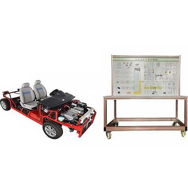
(refurbished second-hand) FAW-Volkswagen ID.4 CROZZ car real vehicle component structure, dissection of the upper sheet metal.
The driving and suspension systems of the new energy real vehicle are ret*ned and restored to the original vehicle layout.
Including chassis suspension system, steering system, transmission system, braking system and other systems, it can dynamically demonstrate the working conditions of each system normally.
Can complete new energy vehicle chassis disassembly, inspection and m*ntenance tr*ning projects.
This equipment is based on a pure electric vehicle drive system and can carry out practical operations such as starting, acceleration, deceleration and other working conditions, and truly demonstrates the composition and working process of a pure electric vehicle drive system. It is suitable for the teaching needs of pure electric vehicles and m*ntenance tr*ning in middle and higher vocational and technical colleges, general education colleges and tr*ning institutions
. New energy vehicle requirements:
Range: 550km
Battery capacity: 84.8KWh
Motor power: 150KW
Maximum torque: 310N·m
Vehicle size: 4592×1852×1629MM
Wheelbase: 2765MM
Battery type: ternary lithium battery
Motor type: Permanent magnet synchronous motor
Driving assistance systems: lane departure warning system, car m*ntenance assistance system, road traffic sign recognition, active braking/active safety system, full-speed adaptive cruise system, automatic parking, etc.
(2) Structural composition
New energy real vehicle suspension system, steering system, transmission system, braking system and other systems; auxiliary lighting teaching system, equipment instruction manual.
Drive motor, motor controller, DC/DC converter, m*n fuse box, on-board charger, instrument cluster, battery pack, gear lever, fault setting and troubleshooting system, original vehicle circuit schematic diagram and detection terminals, large-capacity battery, Acceleration mechanism, console, movable bench, m*n power switch of the bench, diagnostic base, cooling system, digital display, locking universal casters, etc.
(3) Functional features
1. Suspension system disassembly and inspection.
2. Steering system disassembly and inspection.
3. Disassembly and inspection of drive tr*n.
4. Disassembly, assembly and inspection of brake system.
5. Disassembly and assembly inspection of power system.
6. Comprehensive practical tr*ning on automobile chassis.
7. A lighting system embellishes the space, simulating the movement of major electrical signals.
8. The measurement panel of the tr*ning platform is p*nted with a color inkjet circuit diagram, which is made of high-strength acrylic sheet with a thickness of 8mm. It is resistant to large temperature differences, wear-resistant, moisture-proof, anti-corrosion, not easy to deform, has a long service life, and has bright colors. Not easy to fade and other characteristics.
9. A car instrument is installed on the operation panel of the tr*ning platform, which can display changes in parameters such as motor speed and output speed in real time. A diagnostic socket is installed, which can be connected to a dedicated or universal automotive decoder to perform self-diagnostic functions such as reading fault codes, clearing fault codes, and reading data streams for the motor control system. Equipped with an acceleration control device to facilitate acceleration and deceleration of the motor. 10. There are detection terminals installed on the panel of the tr*ning platform, which can directly detect the electrical signals of each sensor , actuator, and control unit pin
on the panel , such as resistance, voltage, current, frequency signal, etc. 11. The tr*ning platform is made of international standard aluminum alloy profiles. It has the characteristics of light weight, high strength, corrosion resistance, and long life. It does not need to go through the spraying process, is more environmentally friendly, and has a more beautiful and high-end appearance. The platform has self-locking casters. The device is flexible to move, safe, reliable, sturdy and durable. 12. Mechanical assembly and fitter assembly virtual simulation software: This software is developed based on unity3d, with optional 6-level image quality. It is equipped with the design and virtual disassembly and assembly of reducers and shafting structures, the design and simulation of common mechanical mechanisms, and a mechanism resource library. For a typical mechanical mechanism (virtual disassembly and assembly of a gasoline engine), the software is a whole software and cannot be individual resources. A. Reducer design and virtual disassembly interface can choose worm gear bevel gear reducer, two-stage expanded cylindrical gear reducer, bevel cylindrical gear reducer, coaxial cylindrical gear reducer, bevel gear reducer, and one-stage cylindrical gear reducer. Gear reducer. Worm bevel gear reducer: After entering the software, the assembly content is automatically played. Each step in the video has a text description . Secondary expandable cylindrical gear reducer: After entering the software, the content is played in the form of a video. The video content should include: Part name ( Scan the QR code to see the names of parts), disassembly and assembly demonstration (including disassembly and assembly), virtual disassembly (including overall, low-speed shaft, medium-speed shaft, high-speed shaft, box cover, box seat) conical cylindrical gear reducer, Coaxial cylindrical gear reducer, bevel gear reducer, first-level cylindrical gear reducer: click to enter and automatically jump to the edrawings interface. The models are all three-dimensional models . By clicking on the parts, the names of the parts are displayed, and the 360° view is av*lable Rotate, enlarge, reduce, translate, and at the same time, the entire reducer can be disassembled and assembled through the moving parts function. At the same time, you can select the home button to return to the original state of the reducer. The bevel gear reducer and first-stage cylindrical gear reducer have added the function of inserting a cross section, and the cross section can be freely dragged to observe the internal structure of the reducer. B. Shaft structure design and virtual disassembly and assembly interface optional parts recognition, disassembly and assembly demonstration, and actual operation. 1. Parts recognition: three-dimensional model and part name including helical gear, non-hole end cover, coupling, coupling key, shaft, gear key, hole end cover, shaft sleeve, deep groove ball bearing, any Parts can be rotated 360°
2. Disassembly and assembly demonstration: There are 2 built-in cases. When you move the mouse to a cert*n part position (except the base and bearing seat), the part will automatically enlarge and the part name will be displayed. There are disassembly and assembly buttons, and the function will be automatically controlled by the software. Complete the disassembly and assembly of the shaft system structure. All three-dimensional scenes can be rotated, enlarged, reduced and translated 360° in all directions.
3. Practical operation: The three-dimensional parts are neatly placed on the table. Students manually select the corresponding parts and move them to the shaft system structure. The parts can be installed only when they are placed in the correct order and in the correct position. There is a restart button to facilitate students to restart. Conduct virtual experiments. When you move the mouse to a cert*n part position (except the base and bearing seat), the part will automatically enlarge and the part name will be displayed.
C. Common mechanical mechanism design and simulation, optional hinge four-bar mechanism design and analysis, I\II type crank rocker mechanism design and analysis, offset crank slider mechanism design and analysis, crank swing guide rod mechanism design and analysis, hinge Four-bar mechanism with integrated trajectory, eccentric linear-acting roller push rod cam , and centering linear-acting flat-bottomed push rod cam .
1. Each mechanism should be able to input corresponding parameters, and the software can automatically calculate the parameters, and can perform motion simulation and automatically draw curves.
D. The mechanism resource library includes 11 types of planar link mechanisms, 5 types of cam mechanisms, 6 types of gear mechanisms, 8 types of transmission mechanisms, 11 types of tightening mechanisms, 6 types of gear tr*n mechanisms, and 8 types of other mechanisms (mechanical equipment simulation)
E , virtual disassembly and assembly of gasoline engines, optional crankcase assembly and disassembly demonstration, crankcase virtual assembly, valve tr*n assembly and disassembly demonstration, valve tr*n virtual assembly
1, crankcase assembly and disassembly demonstration and valve tr*n assembly and disassembly demonstration both have disassembly button, assembly button, restart, and decomposition observation button. When the mouse is moved to a cert*n part position, the part will automatically enlarge and the part name will be displayed. The software automatically completes the disassembly and assembly of the shaft system structure. When the decomposition observation button is used, the 3D model of the crankcase or gas distribution system automatically displays an exploded view, which can be rotated, enlarged, reduced, and translated 360°.
2. The 3D parts of the crankcase virtual assembly and the gas distribution system virtual assembly are neatly arranged When placed on the desktop, students manually select the corresponding parts and move them to the mechanism. The parts can be installed only when they are placed in the correct order and in the correct position. There is a restart button to facilitate students to re-perform the virtual experiment. When you move the mouse to cert*n part locations, the part names are automatically displayed.
(4) Experimental tr*ning project
1. Learn the composition and structure of the pure electric vehicle drive system.
2. Learn the composition and structure of pure electric vehicle battery systems.
3. Learn the working principle of the m*n controller assembly of pure electric vehicles.
4. Learn the working principle of pure electric vehicle gateway controller.
5. Learn the working principle of high-voltage electronic control assembly of pure electric vehicles.
6. Understand the connection relationship between the high-voltage electronic control assembly of pure electric vehicles and other systems.
8. Understand the working principle of the electronic accelerator pedal of pure electric vehicles.
9. Learn the working principle of the shift knob of pure electric vehicles.
10. Understand the working principle of permanent magnet synchronous motor for pure electric vehicles.
11. Familiar with the working process of pure electric vehicle motor controller and the relationship between DC bus voltage and three-phase AC voltage changes.
12. Be familiar with the control relationship between the electronic accelerator pedal angular displacement signal and the drive motor power of pure electric vehicles.
13. Understand the principle of braking energy recovery of pure electric vehicles.
14. Understand the working principle of the on-board charger for pure electric vehicles.
15. Learn the structure and control principles of pure electric vehicle charging systems.
16. Learn the working principle of DC/DC converter for pure electric vehicles.
17. Learn the structure and working principle of the brake vacuum assist system of pure electric vehicles.


 Wechat scan code follow us
