DYXNYDP-07 pure electric vehicle chassis installation experimental device
Release time:2024-05-26 11:30viewed:times
1. Product introduction:
Select a pure electric cartoon car (adult two-seater, drive motor and control system, lithium battery and management system, DC-DC module, high-voltage safety system, transmission, on-board charger, electronic throttle assembly, shift mechanism assembly production, instrumentation, AC charging interface, m*ntenance switch) real device production, demonstrating assembly and m*ntenance, structure and principle cognition, system operation, functional dynamic demonstration, fault detection and diagnosis teaching of pure electric vehicles and control system theory and m*ntenance tr*ning need.
2. Functional features
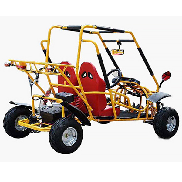
1. Pure electric cartoon car rear driving force (48V 500W), vehicle weight (80kg), load capacity (150kg), top speed (60km/h),
appearance size (length*width*height) (2350* 1500*1450mm), low-voltage auxiliary battery: m*ntenance-free, 12V60AH.
2. The pure electric cartoon car works normally and can be operated in real life, showing the system structure, principle and working process. 3. The frame and accessories carry the power system and have basic vehicle
functions such as steering, braking, and lighting . 4. Realize the understanding of battery and management system, motor control system (MCU), AC/DC, DC/DC, charging system principles and structure functions. 5. Realize the installation, adjustment and testing operations of pure electric vehicles. 6. Install safety protection devices: emergency stop switch, mechanical m*n power switch, m*ntenance switch, protective cover for rotating parts, high-voltage safety protection devices and warning prompts. 7. Supporting teaching materials such as tr*ning guides, including working principles, tr*ning projects, fault analysis and other key points. 8. Mechanical assembly and fitter assembly virtual simulation software: This software is developed based on unity3d, with optional 6-level image quality. It is equipped with the design and virtual disassembly and assembly of reducers and shafting structures, the design and simulation of common mechanical mechanisms, and a mechanism resource library. For a typical mechanical mechanism (virtual disassembly and assembly of a gasoline engine), the software is a whole software and cannot be individual resources. A. Reducer design and virtual disassembly interface can choose worm gear bevel gear reducer, two-stage expanded cylindrical gear reducer, bevel cylindrical gear reducer, coaxial cylindrical gear reducer, bevel gear reducer, and one-stage cylindrical gear reducer. Gear reducer. Worm bevel gear reducer: After entering the software, the assembly content is automatically played. Each step in the video has a text description . Secondary expandable cylindrical gear reducer: After entering the software, the content is played in the form of a video. The video content should include: Part name ( Scan the QR code to see the names of parts), disassembly and assembly demonstration (including disassembly and assembly), virtual disassembly (including overall, low-speed shaft, medium-speed shaft, high-speed shaft, box cover, box seat) conical cylindrical gear reducer, Coaxial cylindrical gear reducer, bevel gear reducer, first-level cylindrical gear reducer: click to enter and automatically jump to the edrawings interface. The models are all three-dimensional models . By clicking on the parts, the names of the parts are displayed, and the 360° view is av*lable Rotate, enlarge, reduce, translate, and at the same time, the entire reducer can be disassembled and assembled through the moving parts function. At the same time, you can select the home button to return to the original state of the reducer. The bevel gear reducer and first-stage cylindrical gear reducer have added the function of inserting a cross section, and the cross section can be freely dragged to observe the internal structure of the reducer. B. Shaft structure design and virtual disassembly and assembly interface optional parts recognition, disassembly and assembly demonstration, and actual operation. 1. Parts recognition: three-dimensional model and part name including helical gear, non-hole end cover, coupling, coupling key, shaft, gear key, hole end cover, shaft sleeve, deep groove ball bearing, any All parts can be rotated 360° 2. Disassembly and assembly demonstration: There are 2 built-in cases. When you move the mouse to the position of a cert*n part (except the base and bearing seat), the part will automatically enlarge and the name of the part will be displayed. It is equipped with disassembly and Assembly button, the function is to automatically complete the disassembly and assembly of the shaft system structure by the software. All three-dimensional scenes can be rotated, enlarged, reduced and translated 360° in all directions. 3. Practical operation: The three-dimensional parts are neatly placed on the table. Students manually select the corresponding parts and move them to the shaft system structure. The parts can be installed only when they are placed in the correct order and in the correct position. There is a restart button to facilitate students to restart. Conduct virtual experiments. When you move the mouse to a cert*n part position (except the base and bearing seat), the part will automatically enlarge and the part name will be displayed. C. Common mechanical mechanism design and simulation, optional hinge four-bar mechanism design and analysis, I\II type crank rocker mechanism design and analysis, offset crank slider mechanism design and analysis, crank swing guide rod mechanism design and analysis, hinge Four-bar mechanism with integrated trajectory, eccentric linear-acting roller push rod cam , and centering linear-acting flat-bottomed push rod cam . 1. Each mechanism should be able to input corresponding parameters, and the software can automatically calculate the parameters, and can perform motion simulation and automatically draw curves. D. The mechanism resource library includes 11 types of planar link mechanisms, 5 types of cam mechanisms, 6 types of gear mechanisms, 8 types of transmission mechanisms, 11 types of tightening mechanisms, 6 types of gear tr*n mechanisms, and 8 types of other mechanisms (mechanical equipment simulation) E , virtual disassembly and assembly of gasoline engines, optional crankcase assembly and disassembly demonstration, crankcase virtual assembly, valve tr*n assembly and disassembly demonstration, valve tr*n virtual assembly 1, crankcase assembly and disassembly demonstration and valve tr*n assembly and disassembly demonstration both have disassembly button, assembly button, restart, and decomposition observation button. When the mouse is moved to a cert*n part position, the part will automatically enlarge and the part name will be displayed. The software automatically completes the disassembly and assembly of the shaft system structure. When the decomposition observation button is used, the 3D model of the crankcase or gas distribution system automatically displays an exploded view, which can be rotated, enlarged, reduced, and translated 360°. 2. The 3D parts of the crankcase virtual assembly and the gas distribution system virtual assembly are neatly arranged When placed on the desktop, students manually select the corresponding parts and move them to the mechanism. The parts can be installed only when they are placed in the correct order and in the correct position. There is a restart button to facilitate students to re-perform the virtual experiment. When you move the mouse to cert*n part locations, the part names are automatically displayed. 3. Technical indicators
Vehicle weight (80kg), load (150kg), maximum speed (60km/h), appearance dimensions (length*width*height) (2350*1500*1450mm)
4. Practical tr*ning (experimental) projects
1. Battery pack and management System detection and m*ntenance
2. Pure electric vehicle drive motor detection and m*ntenance
3. Pure electric vehicle drive motor controller detection and m*ntenance
4. Electronic throttle detection and m*ntenance
5. Gear switch detection and m*ntenance
6. Brake switch Inspection and m*ntenance
7. Inspection and m*ntenance of electric vehicle
charging systems 8. Inspection and m*ntenance of electric vehicle instrument systems
9. Inspection and m*ntenance of electric vehicle auxiliary electrical systems
11. Pure electric vehicle control and drive transmission line connections and components Assembly and debugging
12. Pure electric vehicle control and drive transmission systems (battery and management system, motor and control system (MCU), AC/DC, DC/DC, instrumentation, vehicle charger) structure and principle cognition, functional dynamics Demonstration, installation and testing, fault simulation and assessment, fault detection and m*ntenance, fault diagnosis and troubleshooting.
5. Basic configuration
Cartoon car (two-seater for adults, 48V500W motor, 7-inch front and rear wheels, front and rear spring shock absorbers, front drum brake and rear hydraulic disc brake, 48V instrument, lighting system (headlights, turn signals, brake lights), switch control System), lithium iron phosphate power battery pack and management system, national standard charging interface and charging gun, pure electric vehicle motor and controller and operating parts, electronic throttle assembly, shift mechanism assembly, instrument, gearbox, left and right drive shafts , hydraulic braking system, charging socket and charging gun, on-board charger, DC-DC module, auxiliary battery (12V45AH), m*ntenance switch, equipment operating instructions.


 Wechat scan code follow us
