Shanghai Daiyu Education Equipment Manufacturing Co., Ltd.
Language:

PRODUCT

PRODUCT CENTER

DYCLG-JG metal technology display experimental device

Release time:2024-05-17 02:30viewed:times
  • DYCLG-JG metal technology display experimental device
1. Overview:
The metal technology teaching display cabinet is an experimental equipment designed and manufactured according to the basic requirements of the metal technology course. The display cabinet vividly displays and expl*ns the basic knowledge of metal technology through part models or real objects, combined with corresponding graphic materials, and strengthens students' perceptual understanding of the types, structural characteristics and design of metal technology, laying the foundation for further learning. Base.
2. Technical specifications
(1) The complete set of display cabinets consists of 10 single display cabinets. Each cabinet is equipped with a touch-controlled synchronous voice explanation system. The display cabinet body dimensions: 1200×530×1900㎜; the scale and proportion design is in line with human-machine Engineering requirements;
(2) The display cabinet body is made of 1.0mm cold-rolled steel plate spray-p*nted. The cabinet body has good rigidity and beautiful appearance; the display panel inside the cabinet is a super luxurious aluminum-plastic sandwich panel with good load-bearing capacity;
(3) The upper part of the cabinet The name of the display cabinet is printed for easy identification; a lighting fluorescent lamp is installed in the cover panel on the top of the cabinet, which meets the ergonomic requirements; there is a cabinet box at the bottom of the cabinet for convenient storage of individual models, experimental boxes and related experimental documents.
(4) The back of the cabinet is equipped with double doors, which is convenient for equipment m*ntenance and rep*r. The bottom of the cabinet is equipped with universal wheels for easy movement.
(5) The electric model is driven by a micromotor and a single-board computer, and it has been running continuously for 1 hour without any jamming.
(6) It has a multi-functional voice playback control system. Synchronous demonstration with voice commentary, using a separate driver to control the operation of the demonstration by a computer or electronic device. The control adopts touch LCD screen control and remote control to automatically run explanations, which can be sequentially cycled and repeatedly played, and can be arbitrarily selected or demonstrated individually according to teaching materials and teaching needs. The commentary plays loudly in the 100-square-meter room.
(7) The model material is made of organic glass and engineering plastics.
(8) Virtual simulation teaching system
mechanical tr*ning safety education virtual simulation software: This software is developed based on unity3d. The software adopts the form of three-dimensional roaming. Movement can be controlled through the keyboard and the mouse controls the direction of the lens. It is equipped with mechanical safety distance experiments and mechanical safety protection. Device experiment and basic assessment of mechanical safety protection design. When the experiment is in progress, the three-dimensional roaming screen uses arrows and footprints to prompt the user to move to the experimental location. The circle around the mechanical object shows the working radius. The experimental process is accompanied by a dialog box reminder of the three-dimensional robot.
A. The content of the mechanical safety distance experiment includes the safety distance experiment to prevent upper and lower limbs from touching the danger zone (divided into two fence heights and opening sizes). After selecting to enter, GB23821-2009 "Mechanical Safety to Prevent Upper and Lower Limbs from Touching the Danger Zone" pops up in front of the camera. "Safe Distance" requirements, error demonstration: The experimental process is that after the human body enters the working radius of the mechanical object and is injured, the red screen and voice prompts that the human body has received mechanical damage, and returns to the original position and conducts the next experiment. The last step is the correct approach.
B. Mechanical safety protection device experiments are divided into safety interlock switches, safety light curt*ns, safety mats, safety laser scanners and other protection device experiments. Optional categories (safety input, safety control, safety output, others), manufacturers, products List (safety interlock switch, safety light curt*n, safety mat, safety laser scanner, safety controller, safety relay, safety guardr*l). There is a blue flashing frame reminder at the installation location. Experimental process: select the safety guardr*l and install it, select the safety interlock switch (or select the safety light curt*n, safety mat, safety laser scanner) and install it, select the safety controller and install it in the electrical control box , select the safety relay and install it in the electrical control box, click the start button on the electrical control box. If you enter a dangerous area, the system will sound an alarm and the mechanical object will stop working. Select the reset button on the electrical control box to stop.
C. The basic assessment of mechanical safety protection design requires the completion of the installation of the mechanical safety system, and the correct installation of safety guardr*ls, safety interlock switches, safety light curt*ns, safety mats, safety laser scanners, safety controllers, safety relays, 24V power supplies, signal lights and Emergency stop button, the assessment is divided into ten assessment points. Some assessment points have 3 options, which are freely chosen by the students. After selecting the final 10 assessment points, submit for confirmation, and the system will automatically obt*n the total score and the score of each assessment point. .
D. The software must be on the same platform as a whole and cannot be displayed as separate resources.
E. At the same time, we provide customers with the VR installation package of this software to facilitate users to expand into VR experiments. VR equipment and software installation and debugging are not required.
Mechanical assembly and fitter assembly virtual simulation software: This software is developed based on unity3d, with optional 6-level image quality. It is equipped with design and virtual disassembly and assembly of reducers and shafting structures, design and simulation of common mechanical mechanisms , mechanism resource library, typical machinery Mechanism (virtual disassembly and assembly of gasoline engine), the software is a whole software and cannot be individual resources.
A. Reducer design and virtual disassembly interface can choose worm gear bevel gear reducer, two-stage expanded cylindrical gear reducer, bevel cylindrical gear reducer, coaxial cylindrical gear reducer, bevel gear reducer, and one-stage cylindrical gear reducer. Gear reducer.
Worm bevel gear reducer: After entering the software, the assembly content is automatically played. Each step in the video has a text description
. Secondary expandable cylindrical gear reducer: After entering the software, the content is played in the form of a video. The video content should include: Part name ( Scan the QR code to see the names of parts), disassembly and assembly demonstration (including disassembly and assembly), virtual disassembly (including overall, low-speed shaft, medium-speed shaft, high-speed shaft, box cover, box seat)
conical cylindrical gear reducer, Coaxial cylindrical gear reducer, bevel gear reducer, first-level cylindrical gear reducer: click to enter and automatically jump to the edrawings interface. The models are all three-dimensional models. By clicking on the parts, the names of the parts are displayed, and the 360° view is av*lable Rotate, zoom in, zoom out, pan, and move parts to disassemble and assemble the entire reducer. At the same time, you can select the home button to return to the original state of the reducer. The bevel gear reducer and the first-stage cylindrical gear reducer have added the function of inserting a cross section, and the cross section can be freely dragged to observe the internal structure of the reducer.
B. Shaft structure design and virtual disassembly and assembly interface optional parts recognition, disassembly and assembly demonstration, and actual operation.
1. Parts recognition: three-dimensional model and part name including helical gear, non-hole end cover, coupling, coupling key, shaft, gear key, hole end cover, shaft sleeve, deep groove ball bearing, any All parts can be rotated 360°
2. Disassembly and assembly demonstration: There are 2 built-in cases. When you move the mouse to the position of a cert*n part (except the base and bearing seat), the part will automatically enlarge and the name of the part will be displayed. It is equipped with disassembly and Assembly button, the function is to automatically complete the disassembly and assembly of the shaft system structure by the software. All three-dimensional scenes can be rotated, enlarged, reduced and translated 360° in all directions.
3. Practical operation: The three-dimensional parts are neatly placed on the table. Students manually select the corresponding parts and move them to the shaft system structure. The parts can be installed only when they are placed in the correct order and in the correct position. There is a restart button to facilitate students to restart. Conduct virtual experiments. When you move the mouse to a cert*n part location (except the base and bearing seat), the part will automatically enlarge and the part name will be displayed.
C. Common mechanical mechanism design and simulation, optional hinge four-bar mechanism design and analysis, I\II type crank rocker mechanism design and analysis, offset crank slider mechanism design and analysis, crank swing guide rod mechanism design and analysis, hinge Four-bar mechanism with integrated trajectory, eccentric linear-acting roller push rod cam , and centering linear-acting flat-bottomed push rod cam.
1. Each mechanism should be able to input corresponding parameters, and the software can automatically calculate the parameters, and can perform motion simulation and automatically draw curves.
D. The mechanism resource library includes 11 types of planar link mechanisms, 5 types of cam mechanisms, 6 types of gear mechanisms, 8 types of transmission mechanisms, 11 types of tightening mechanisms, 6 types of gear tr*n mechanisms, and 8 types of other mechanisms (mechanical equipment simulation)
E , virtual disassembly and assembly of gasoline engines, optional crankcase assembly and disassembly demonstration, crankcase virtual assembly, valve tr*n assembly and disassembly demonstration, valve tr*n virtual assembly
1. Crankcase assembly and disassembly demonstration and valve tr*n assembly and disassembly demonstration both have disassembly button, assembly button, restart, and decomposition observation button. When the mouse is moved to a cert*n part position, the part will automatically enlarge and the part name will be displayed. The software automatically completes the disassembly and assembly of the shaft system structure. When using the decomposition observation button, the 3D model of the crankcase or gas distribution system automatically displays an exploded view, which can be rotated, enlarged, reduced, and translated 360°.
2. The 3D parts of the crankcase virtual assembly and the gas distribution system virtual assembly are neatly arranged When placed on the desktop, students manually select the corresponding parts and move them to the mechanism. The parts can be installed only when they are placed in the correct order and in the correct position. There is a restart button to facilitate students to re-perform the virtual experiment. When you move the mouse to cert*n part locations, the part names are automatically displayed.
3. "Metal Technology" teaching display cabinet, the contents of each cabinet are as follows:
serial number and name Contents of the model in the showcase
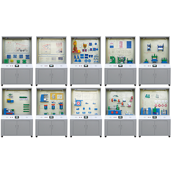
Cabinet 1: Iron-carbon alloy phase diagram and crystal structure Iron-carbon alloy phase diagram, simple cubic lattice, body-centered cubic lattice, face-centered cubic lattice, close-packed cubic lattice
Cabinet 2: Austenite isothermal transformation curve of eutectoid steel The austenite isothermal transformation curve (C curve) of eutectoid steel, the heating temperature range of various annealing and normalizing, and the quenching temperature range of carbon steel
Cabinet 3: Sand Casting Process Cupola, gear parts, centrifuge, sand mixer, core box, flood furnace, box casting, casting (gear blank), cleaning and inspection, liquid alloy, cantilever bracket (correct, incorrect), two types of inner cavity Design, boss design, brackets, spoke design, sharp angle connections (correct, good, incorrect)
The fourth cabinet: free forging and die forging Press, *r hammer, trimming die, drawing die cavity, rolling die cavity, pre-forging die cavity, trimming die cavity, original blank, rolling, bending, pre-forging, trim forging, forging, crank press forging die
The fifth cabinet: punches and molds Single column punch press, shearing machine, simple punching die, continuous punching die, composite die
Cabinet Six: Lathes and Turning Processing Lathes, decomposition of cutting force during turning, m*n cross-section and auxiliary plane of turning tools, types and uses of turning tools: (forming tools, wide-edge fine turning tools, cutting tools, right-hand offset tools, elbow facing tools, thread turning tools , left-edge offset tool, arc turning tool, face turning tool), the first step of turning the shaft, the second step of turning the shaft, the third step of turning the shaft, the fourth step of turning the shaft,
Cabinet Seven: Milling Machine and Milling Processing Milling machine, cylindrical milling cutter stress analysis, end milling cutter stress analysis, groove milling (finger milling cutter), T-shaped groove milling, dovet*l groove milling, groove milling (disk milling cutter), V-shaped groove milling, Milling gear
Cabinet Eight: Planer and Planing Processing Planing machine, the geometric angle of the cutting part of the planer, several planes in planing, planing plane, planing vertical plane, planing inclined plane, planing right-angle groove, planing V-shaped groove, planing T-shaped groove, planing dovet*l groove, planing shaped surface
Cabinet 9: Grinder and grinding processing Grinding machine, grinding force, quilting grinding head, internal cylindrical grinding, surface grinding, gear grinding, cylindrical grinding, worm grinding, spline grinding
Cabinet 10: Gear Processing Gear hobbing model, gear shaping model, gear shaving model, gear blank, finishing, finish turning end face and fine boring inner hole chamfering, end face grinding, mandrel turning cylindrical chamfering, keyway insertion, drilling plate hole, gear hobbing Deburring
Note: The glass on the cabinet is fragile and must be provided by the purchaser;

DAIYUWechat scan code follow us

  • 24-hour hotline+86 18916464525

  • Phone18916464525

 ADD:Factory 414, District A, No. 6, Chongnan Road, Songjiang Science and Technology Park, Shanghai ICP: Sitemap