Shanghai Daiyu Education Equipment Manufacturing Co., Ltd.
Language:


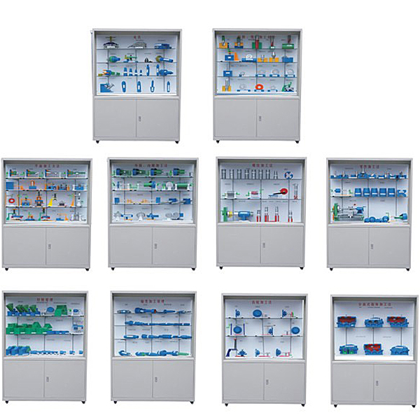


| serial number and name | Contents of the model in the showcase |
| Cabinet No. 1: Fixtures |
Four-jaw chucks and wrenches, machine vises and wrenches, floating reamer chucks, drill chucks and keys, quick-change drill chucks, fixed drill press clamps, screw plate clamping, elastic rotary centers, automatic clamping cards Claw drill bit set (4 types), ordinary center, half center, reverse center, big head center, long neck center, carbide center |
| The second cabinet: drilling and milling processing applications |
Drilling, boring, enlarging, reaming, tapping, str*ght shank Morse cone reamer, cylindrical milling cutter, plane milling, serrated milling cutter, end mill, keyway milling cutter, half-circle keyway milling cutter, angle milling Knife, three-sided edge milling cutter, staggered three-sided edge milling cutter, solid end mill, carbide end mill, form milling cutter, countersunk cylindrical counterbore, countersunk tapered counterbore, countersunk boss plane |
| The third cabinet: plane processing | Turning outer circle, turning end face, turning handle, thread turning, plane planing, planing hole processing, planing rack, milling steps, milling V-shaped grooves, milling gears, milling special-shaped surfaces, inserting gears, latch keys, flower arrangement Key, inserted ring gear, surface grinding, surface grinding, spline grinding, thread grinding |
| The fourth cabinet: outer circle and inner hole processing method |
Cylindrical turning, cone turning, inner circle turning of through holes, inner circle turning of closed holes, external cylindrical grinding, internal circle grinding, form grinding, centerless grinding, boring of through holes, boring of closed holes, broaching of rectangular flowers Key, broaching inner hole, flat body forming turning tool, prism forming turning tool, circular forming turning tool |
| Cabinet Five: Thread Processing Method | 8 thread types, hand taps, machine taps, nut taps, tapered taps, die taps, spiral flute taps, round die, cyclone cutting device, thread rolling principle, thread rolling principle, comb thread milling cutter |
| Cabinet Six: Parts Processing Method | Parts grinding, cylindrical grinding parts, V-frame milling, dovet*l grooves and dovet*l blocks and their milling steps, internal cylindrical grinding and their parts, thread processing structures |
| Cabinet Seven: Cutting Principles |
The edge inclination angle of the turning tool, the cutting force component during turning, the cutting plane and the base surface (horizontal turning), the cutting plane and the base surface (longitudinal turning), the generation and growth of built-up edge (3 items), and the formation of scales (4 items) ), heat generation temperature distribution on the tool and workpiece, basic cutting form (4 items), uses of commonly used turning tools, tool wear patterns (3 items) |
| Cabinet Eight: Principles of Shaft Processing |
Hollow shaft, grinding wheel spindle of grinding machine, internal grinding tool spindle, eccentric shaft, crankshaft, cylindrical spindle, ordinary cone spindle, cone spindle with nut, worm shaft, step spindle, machine tool spindle, spline spindle, belt Keyway drive shaft, oil injection pump drive shaft, optical shaft, stepped shaft, double cone spring spindle |
| Cabinet 9: Gear Processing Method | Blanks, turning gear blanks, drilling inner holes, milling gears, shaping gears, planing gears, chamfering, turning internal circles, broaching rectangular splines |
| Cabinet 10: Separate box processing method | Marking, machining the bottom surface, splitting or planing the end surface, drilling, tapping, milling and countersunk head base, completed machine cover and machine base |
 Wechat scan code follow us

24-hour hotline+86 18916464525

Phone18916464525
ADD:Factory 414, District A, No. 6, Chongnan Road, Songjiang Science and Technology Park, Shanghai ICP: Sitemap