Shanghai Daiyu Education Equipment Manufacturing Co., Ltd.
Language:


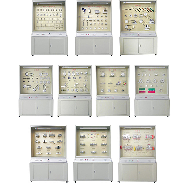


| serial number | Showcase display content det*ls |
| 1. Type of threaded connection |
A. Types of threads (10 types) Coarse thread, ordinary thread, fine thread, ordinary thread, cylindrical pipe thread, conical thread, conical pipe thread, rectangular thread, trapezoidal thread, zigzag thread, left-hand and right-hand thread B. Basic types, pictures of m*n parameters C. Basic thread connection Types (8 types) ordinary bolt connection, double-headed stud connection, screw connection, set screw connection, eye screw connection, T-slot screw connection, anchor screw connection, matching bolt connection standard connection parts (24 pieces) on the photo ( 27 pieces) Hex head bolts, bolts, screws, set screws, self-tapping screws, hex nuts, round nuts, stop washers, bevel washers, washers |
| 2. Application of threaded connection |
A. Threaded connection applications (3 pieces) opening and closing nuts, vise (actual), screw jack B. Threaded connection anti-loosening (10 pieces) counter nuts, self-locking nuts, spring washers, cotter pins and slotted nuts , stop washer, gasket, series steel wire, series steel wire (wrong), punch point, end rivet C, threaded connection preload (2 pieces) torque measuring wrench, fixed torque wrench D, strength improvement measures (12 pieces) all Nut-loaded structure, spherical washer, w*st bolt, hollow bolt, suspension nut, cylinder sealing components: soft gasket seal, sealing ring seal, spring washer, w*st ring bolt connection |
| 3. Key, spline and keyless connection |
A. Key connection types (11 pieces) and pictures (fine-tooth spline) Ordinary flat key connection: round head flat key, square head flat key, semi-round head flat key guide flat key connection, sliding key connection, semi-round key connection wedge key Connection: round head wedge key, square head wedge key, hook head wedge key, tangential key connection B, spline connection type (3 pieces) rectangular spline connection involute spline connection triangle spline connection C, keyless connection type (2 pieces) Profile connection (1) Profile connection (2) D. Pin connection type (10 pieces) safety pin, connection pin, screw taper pin (taper pin with thread at the end), open t*l taper pin pin type Parts (standard parts) (cylindrical pins, tapered pins, screw-t*led tapered pins, internally threaded tapered pins, grooved pins, cotter pins) |
| 4. Riveting, welding, gluing and interference fit connection |
A. Riveting (10 pieces) lap joints, single cover butt joints, double cover butt joints, commonly used rivet types after riveting Welding (5 pieces) front fillet welds, lap fillet welds , butt welds, plug welds, edge welds C, glued joints (15 pieces) plate joints, cylindrical joints, corner joints, tapered and blind hole joints D, interference fit connections (4 pieces) press fit connections , structure of press-fit components, crankshaft press-fit assembly, gear press-fit connection |
| 5. Belt drive |
A. Belt drive type (4 pieces) flat belt drive V-belt drive synchronous belt drive staggered shaft drive B. Belt type (9 pieces) O, A, B, C, D synchronous, flat belt, V-joint, multi-wedge Belt C. Pulley structure (4 pieces) Solid V-belt pulley Web type V-belt pulley Hole plate type V-belt pulley spoke type V-belt pulley D. Tensioning device (3 pieces) Regular tensioning, self-weight type automatic Tensioning, tensioning wheel tensioning |
| 6. Ch*n drive |
A. Ch*n drive components (1 piece) ch*n, driving sprocket, driven sprocket B. Ch*n drive motion characteristics polygon effect model C. Sprocket structure (4 pieces) integral sprocket, orifice sprocket, and ring gear welding Type sprocket, ring gear screw-connected sprocket D. Transmission ch*n type (4 pieces) Single-row roller ch*n Double-row roller ch*n toothed ch*n E. Ch*n drive tensioning device (3 pieces) The tensioning wheel is regularly adjusted and tensioned Automatic tensioning of tension wheel, pressure plate and pallet tensioning |
| 7. Gear transmission |
A. Basic types of gear transmission (6 pieces) spur gear transmission, helical gear transmission, herringbone gear transmission, rack and pinion transmission, spur bevel gear transmission, curved bevel gear transmission B. Gear tooth f*lure modes (5 types) teeth Surface pitting, gear tooth breakage, tooth surface gluing, tooth surface wear, plastic deformation C. Gear tooth stress analysis (3 pieces) Spur gear transmission stress analysis Helical gear transmission stress analysis bevel gear transmission D. Gear Structure (5 pieces) Gear shaft Solid gear Web type structure Reinforced web type structure Spoke type gear |
| 8. Worm drive |
A. Worm transmission type (3 pieces) Ordinary cylindrical worm drive, arc worm drive, bevel worm drive, multi-head worm B. Worm gear structure (4 pieces) ring gear worm gear, integral cast worm gear, bolted worm gear, split-cast worm gear C. Worm structure (2 pieces) worm with undercut and worm without undercut D. Stress analysis (2 pieces) Worm gear stress analysis, worm stress analysis |
| 9. Rolling bearing types |
A. M*n types of rolling bearings (10 pieces) spherical ball bearings, spherical roller bearings, tapered roller bearings, one-way thrust ball bearings, two-way thrust ball bearings, deep groove ball bearings, angular contact ball bearings, thrust cylindrical rollers Bearings, cylindrical roller bearings, needle roller bearings. B. Bearing code table C. Comparison of diameter and width series (2 pieces) Comparison of diameter series Comparison of width series D. Rolling bearing structure Actual bearing structure, outer ring, rolling element, cage, inner ring |
| 10. Sliding bearings |
A. Centripetal sliding bearings (5 pieces) split sliding bearings, integral sliding bearings, multi-oil wedge bearings, sliding bearings with sleeves, tilting bearings B. Push sliding bearings (4 pieces) solid type, single ring Type, hollow type, multi-ring type C. Bearing structure (3 pieces) Integral type, split type, bimetal bearing D. Working condition of dynamic pressure bearing (picture) |
| 11. Design of rolling bearing device |
A. Bearing fastening (picture) B. Typical structure of bearing device (6 pieces) spur gear bearing parts, helical gear bearing parts, small bevel gear bearing parts (front and reverse installation), worm bearing parts (fixed at both ends), worm Bearing components (one end is fixed and the other is swimming), herringbone gear bearing component C, bearing preload (picture) |
| 12. Coupling |
A. Rigid coupling (2 pieces) sleeve type coupling, flange type coupling B. Flexible coupling without elastic element (4 pieces) cross slide coupling, double universal coupling, Gear coupling, sprocket coupling C, non-metal elastic element flexible coupling (4 pieces) tire coupling, star elastic coupling, plum blossom coupling, elastic sleeve pin coupling device |
| 13. Clutch |
A. Mechanically operated clutch (5 pieces) tooth clutch, tooth clutch, single-disc friction clutch, multi-disc friction clutch, cone friction clutch B. Automatic clutch (3 pieces) overrunning clutch, brake block centrifugal clutch, ball safety clutch |
| 14. Analysis and design of shafts |
A. Type of shaft (5 pieces) smooth shaft, stepped shaft, hollow shaft, crankshaft, steel wire flexible shaft B. Positioning of parts on the shaft (4 pieces) sleeve round nut compression, set screw fixation, spring ret*ning ring positioning, Conical shaft end positioning C, shaft structural design (4 pieces) model of the first, second and third steps |
| 15. Spring |
A. Spring types (10 categories) variable pitch compression springs, circular cross-section compression springs, tension springs, torsion springs, single-ear leaf springs, conical spiral springs, disc springs, plane vortex springs, annular springs, rubber springs B. Spring classification Figure C, spring application examples (4 pieces) disc springs, clock springs, automobile shock absorber springs, combined compression springs D, cylindrical coil springs (8 pieces) LⅠ type, LⅡ type, LⅢ type, LⅣ type, LⅤ type , LⅥ type, LⅦ type, LⅧ type (a total of 8 physical objects) E. Other types of springs (4 pieces) NⅠ type, NⅡ type, NⅢ type, NⅣ type |
| 16. Reducer |
A. Reducer type and structure (4 units) single-stage cylindrical gear reducer, single-stage bevel gear reducer, single-stage worm gear reducer, double-stage cylindrical gear reducer B. Reducer accessories (8 pieces) Lifting ear hook, oil mark, lifting ring, cover screw, pin, breather, screw plug, sight hole and sight hole cover C, accessories list |
| 17. Lubrication and sealing |
A. Oil cups for lubrication (5 pieces) str*ght-through pressure oil cups, screw-cap oil cups, press-fit pressure oil cups, spring cover oil cups, needle valve type glass oil cups B. Sealing applications (2 pieces) O Shape sealing ring application, Y-shape sealing ring C, standard seals (6 pieces) O-shape sealing ring, J-shape sealing ring, U-shape sealing ring, sealing ring for YX hole, sealing ring for YX shaft, dust ring seal D , contact seal (4 pieces) felt ring oil seal, lip seal ring seal, rubber seal E, non-contact seal (3 pieces) gap seal, sealing ring seal, curved road seal |
| 18. Small mechanical structure design examples |
A. Small machinery (9 units) electric scissors, electric planer, juicer, household dough press, grinder, table fan, engraving machine, angle grinder, electric hand drill |
 Wechat scan code follow us

24-hour hotline+86 18916464525

Phone18916464525
ADD:Factory 414, District A, No. 6, Chongnan Road, Songjiang Science and Technology Park, Shanghai ICP: Sitemap