Shanghai Daiyu Education Equipment Manufacturing Co., Ltd.
Language:


| Serial number and name | Display case contents |
| m*n console | Microcomputer touch LCD screen control, voltage display meter, speaker. |
|
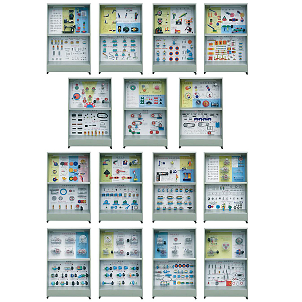
Cabinet 1 Machinery and Mechanism |
Foreword, internal combustion engine, steam engine, sewing machine, bullhead planer, spherical high p*r, spiral p*r, moving p*r, curved p*r, spherical p*r, cylindrical p*r, rotating p*r |
|
Cabinet 2: Basic form of planar linkage mechanism |
Hinge four-bar mechanism: 2 pieces of crank-rocker mechanism, 2 pieces of double-crank mechanism, and 2 pieces of double-rocker mechanism. Single moving p*r mechanism: crank slider mechanism, crank rocker mechanism, rotating guide rod mechanism, moving guide rod mechanism. Double moving p*r mechanism: crank moving guide mechanism, double slider mechanism, double rotating block mechanism |
|
The third cabinet plane linkage mechanism |
Mechanism movement diagram: 2 pumps, 2 pump diagrams, jaw crusher and the diagram. Linkage mechanism: flying shear, bale press, flipping mechanism, photo lift, balance, crane. |
|
Cabinet 4: Form of cam mechanism |
3 pieces of disc cam: roller, tip, plane, moving cam wheel, groove cam mechanism, cross groove cam mechanism, equal diameter cam mechanism, equal width cam mechanism, m*n return cam mechanism, spherical cam mechanism, conical cam mechanism, cylinder Cam mechanism. |
|
Various types of gear transmission in the fifth cabinet |
Parallel shaft transmission: external spur gear mechanism, internal spur gear mechanism, spur gear rack mechanism, helical cylindrical gear mechanism, herringbone cylindrical gear mechanism. Intersecting gear transmission: str*ght bevel gear mechanism, hyperbolic bevel gear mechanism, helical bevel gear mechanism. Phase-shifted shaft transmission: helical gear mechanism, helical rack and pinion mechanism, cylindrical worm and worm gear mechanism, arc worm and worm gear mechanism. |
|
Cabinet Six Basic Properties of Gears |
The names of each part of the involute gear, the formation of the Zhejiang line, the formation of the cycloid, the number of teeth, the module, the pressure solution, and the tooth height coefficient. |
|
Cabinet Seven: The basic formation of the gear tr*n |
The epicyclic gear tr*n, differential gear tr*n, planetary gear tr*n, and fixed axis gear tr*n are combined into one to obt*n a large transmission ratio to achieve specific motion, synthesis of motion, rotation line, used for transmission, decomposition of motion, and harmonic motion deceleration It has two actions: cycloidal pinwheel planetary reducer and automobile differential. |
|
Cabinet Eight Intermittent Motion Mechanism |
2 pieces of gear ratchet mechanism, friction ratchet mechanism, external meshing sheave mechanism, internal sheave mechanism, spherical sheave mechanism, involute incomplete gear mechanism, cycloid incomplete gear mechanism (2 pieces), cam 2 pieces of intermittent mechanism, stop link mechanism, stop guide rod mechanism |
|
The ninth cabinet combination mechanism |
Series combination: stroke expansion mechanism, reversing transmission mechanism. Parallel combination : gear connecting rod curve, 2 mechanisms for experimental given trajectory, mechanism for experimental variable speed motion, coaxial sheave mechanism, error correction mechanism, electric horse amusement machine device. |
|
The 10th Mechanism Space Linkage Mechanism |
Four-bar structure in space: RSSR space four-bar mechanism, RCCR coupling, single universal joint, double universal joint, 4R kneading mechanism, RRSRR angle-driven space five-bar mechanism, and space six-bar Salette mechanism. |
|
Cabinet 11, first-level cylindrical gear reducer |
Spur gear reducer, helical gear reducer, herringbone gear reducer, gear, shaft, gear shaft, machine cover, machine base |
|
Cabinet 12 Two-stage cylindrical gear reducer |
Two-stage expandable cylindrical gear reducer, overhead crane reducer, split-flow two-stage cylindrical gear reducer, coaxial two-stage cylindrical reducer with large end cover structure, coaxial expandable cylindrical gear reducer |
|
Cabinet 13 Three-stage reducer |
Shaft-mounted two-stage gear reducer, vertical two-stage gear reducer, double worm reducer, conical cylindrical gear reducer, gear worm reducer, worm gear reducer |
|
Cabinet Fourteenth Worm Reducer |
Bottom-mounted worm reducer, upper-mounted worm reducer, vertical worm reducer with conical friction clutch, split vertical worm reducer, vertical integral worm reducer, worm, worm shaft |
|
Cabinet 15 Typical reducer |
Harmonic gear reducer, first-stage bevel gear reducer, planetary gear reducer, cycloidal pinwheel reducer, small tooth difference involute planetary gear reducer |
| Serial number and name | Display case contents |
|
Cabinet 1: Basic contents of threaded connections |
Thread types: ordinary thread, trapezoidal thread, rectangular thread, zigzag thread, arc pipe thread, cylindrical pipe thread, conical pipe thread, right-hand thread, left-hand thread, double thread, triple thread. Types of threaded connections: bolted connection, stud connection, screw connection, fastening screw connection. 11 bolts, 4 studs, 9 screws, 5 set screws, 12 nuts, and 7 washers. |
|
Second cabinet threaded connection |
Friction and anti-loosening: top nut, locking hot ring closing anti-loosening nut, slit closing, with nylon ring anti-loosening nut and spring washer. Mechanical anti-loosening: stop washer, stop washer ring and round nut, cotter pin and hexagonal slotted nut, series wire. Load relief devices for transverse load interception: inclined washers, bosses, countersunk pits, load relief sleeves, load relief keys, and interception relief pins. Measures to improve the connection strength: add elastic components, internally inclined nuts, hollow bolts, w*st-shaped rod bolts, large fillet bolts, undercut nuts, and assembly and disassembly of threaded connections. |
|
Cabinet 3 Key, spline and pin connection |
Key connection: ordinary flat key, semicircular key, wedge key, guide flat key, tangential key, saddle sliding key. Spline connection: 3 pieces of rectangular splines, 2 pieces of involute splines. Triangular spline. Pin connection: 3 pieces of cylindrical pins, 4 pieces of conical pins, 3 pieces of guide pins, 3 pieces of safety pins, positioning, connection, safety. |
|
Cabinet 4: Riveting, welding, gluing and interference joints |
Riveting: commonly used rivet types, lap joints, single lap plate butt joints, double lap plate butt joints, and combined joints. Welding: groove type, lap joint, butt joint, corner joint. Bonding: plate joint, pipe joint, corner joint. Interference connection: cylindrical interference connection, conical interference connection. |
|
The m*n types of belt drives in the fifth cabinet |
Materials and joints of flat belts: leather belts, br*ded belts, canvas flat belts, high-speed ring tapes, nylon sheet composite belts, bevel joints, bevel step joints, tape joints, suture joints, leather thread joints. The structure and model of V-belts: O-type, A-type, B-type, C-type, D-type, E-type, wide V-belt, narrow V-belt, flexible V-belt, other transmission belts, combined V-belt, ordinary V-belt, double Surface V-belt, multi-V belt, round belt, trapezoidal toothed synchronous belt. The structure of the pulley: solid pulley, spoked pulley, orifice pulley, elliptical spoked pulley, flat pulley, high-speed pulley, synchronous pulley. |
|
Cabinet Sixth Belt Drive |
V-belt transmission: automatic tensioning device, slide type periodic tensioning device, swing frame type periodic tensioning device, tensioning wheel tensioning device. Flat belt drive: tensioner device, synchronous belt drive |
|
The seventh cabinet ch*n drive |
Transmission ch*n: roller ch*n, inner ch*n plate and sleeve, roller, outer ch*n plate pin, inner ch*n plate, outer ch*n plate, single-pitch double-row roller ch*n, single-row single-pitch roller ch*n, spring Type, spring ret*ning ring, steel wire, cotter pin, transition link, integral sprocket with strap, integral plate type, hole plate type, toothed ch*n with inner guide piece, toothed ch*n with outer guide piece, round pin type, Arrangement and tensioning of roller type, key column type, bearing type, square ch*n, flat top ch*n, circular ch*n and ch*n drive. |
|
Cabinet Eight Gear and Worm Transmission |
The structure of the gear: 2 gear shafts, 2 solid gears, 2 web gears, and spoke gears. Types of worms: Archimedean cylindrical worm, normal str*ght profile worm, linear toroidal worm. The structure of the worm: integral worm gear, hoop worm gear, bolted worm gear, cast-in worm gear, gear transmission. |
|
Cabinet 9 Sliding Bearing |
Materials of bearing bush and lining: bearing alloy, bronze, brass, gray cast iron, miniature bearing, rubber, nylon, PTFE, phenolic resin. The structural form of the oil tank is 5 pieces, and the form of the push bearing: solid, hollow, single ring, multi-ring. The structure of the sliding shaft: overall lined positive sliding bearing, split positive sliding bearing, split oblique sliding bearing, self-aligning sliding bearing, fixed pad thrust bearing, self-aligning sliding bearing, tiltable three-reverse bearing, Connecting rod, hydrostatic bearing. |
|
Cabinet 10 Rolling Bearings |
Inner ring, cage, outer ring, balls, short cylindrical rollers, long cylindrical rollers, threaded rollers, tapered rollers, drum rollers, needle rollers. Types and codes: deep groove ball bearings, spherical ball bearings, spherical roller bearings, cylindrical roller bearings, needle roller bearings, spiral roller bearings, angular contact bearings, tapered roller bearings, thrust ball bearings, thrust rollers bearings. Dimension series: diameter series, inner ring fixed and outer ring rotating, outer ring fixed and inner ring rotating, rolling bearing installation method, rolling bearing disassembly process, inner diameter series 7 pieces, width series 4 pieces. |
|
Cabinet 11 Rolling bearing combination design |
Fixing methods of the inner ring: spring ret*ning ring, shaft end pressure plate, round nut, tapered sleeve. The fixing method of the outer ring: bearing end cover, elastic ret*ning ring for the hole, end cover hole shoulder combination, and sleeve cup. Combination design: 3 pieces with fixed ends, 2 pieces with floating ends, and 2 pieces with one end fixed and one free. Tightening and adjustment: adjustment of rolling bearings and tightening of rolling bearings. Seals: Felt type, cup type, annular gap type, labyrinth type, thread type, bearing seat |
|
Cabinet 12 Coupling |
Elastic sleeve pin coupling, elastic pin coupling, tire coupling, flange coupling, sleeve coupling, clamp coupling, gear coupling, ch*n coupling, cross Axis universal coupling, slider coupling, shear pin safety coupling. |
|
Cabinet Thirteen Clutch |
Teeth clutches include rectangular teeth, trapezoids, equilateral triangle teeth, sawtooth clutches, single disc friction clutches, conical friction clutches, multi-disc friction clutches, tooth-type safety clutches, centrifugal clutches, and overrunning clutches. |
|
Cabinet 14 Types of Shafts and Fixing Methods of Parts on Shafts |
Rotating shaft, spindle, transmission shaft, gear shaft, keyed shaft, worm shaft, crankshaft, camshaft, flexible shaft, structural design of shaft, key connection, spline connection, formed connection, pin connection, interference connection, shaft Shoulder - circlip, shoulder - round nut, shoulder - double round nut, shoulder - sleeve, shoulder - circlip 2 years, conical shaft head - shaft end ret*ning ring, shaft end baffle, double Locking ret*ning ring, slotted clamping connection, hub part clamping connection, elastic sleeve connection, elastic ring connection, elastic disk connection. |
|
Cabinet 15 Spring, Lubrication and Seals |
Tension springs: circular shackle, semi-circular shackle, eccentric circular shackle, tapered closed end spring, adjustable tension spring. Compression springs: springs with flattened end faces, springs with unflattened end faces, rectangular cross-section compression springs, convex springs, concave springs, and conical spiral springs. Torsion springs: outer arm torsion spring, inner arm torsion spring, center arm torsion spring, double torsion spring. Other springs: disc springs, serpentine springs, flat scroll springs, leaf springs. Parallel combination spring, in-line combination spring, conversion mechanism. Lubrication device: press-fit pressure oil cup, oil rope type cup, joint type pressure oil cup, str*ght-through oil cup, oil mark. Seals: 2 pieces of O-type rubber seals, 2 pieces of rectangular rubber seals, nylon gaskets, asbestos gaskets, metal flat gaskets, metal octagonal gaskets, metal toothed gaskets, cutouts: insert lap joints, piston rings , Cut: oblique overlap, double-port oil seal, T-type oil seal, Y-type oil seal, V-type oil seal. 8 pieces of lubricant, oil gun, butter gun. |
 Wechat scan code follow us

24-hour hotline+86 18916464525

Phone18916464525
ADD:Factory 414, District A, No. 6, Chongnan Road, Songjiang Science and Technology Park, Shanghai ICP: Sitemap