Shanghai Daiyu Education Equipment Manufacturing Co., Ltd.
Language:

PRODUCT

PRODUCT CENTER

DYCLG-LJB Machinery Parts Exhibition Training Device

Release time:2024-05-16 08:30viewed:times
  • DYCLG-LJB Machinery Parts Exhibition Training Device
1. Overview
Our company specializes in the production of mechanical series display cabinets . In order to meet the needs of teaching, the teaching *d products are gradually moving towards modern development.
The mechanical parts teaching display cabinet is divided into 20 cabinets with more than 400 models of mechanical parts . The cabinet is welded with SPCC cold-rolled panels (or aluminum-wood structure), which is strong and beautiful. The surface is made of medium-temperature phosphating anti-rust p*nt, flat p*nt, and electrostatic spraying. The model material is made of imported organic boards. The board is equipped with necessary charts and text descriptions. The demonstration image is realistic, the operation is reliable, and the production process is beautiful. Using this display cabinet can improve the teaching effect and save class time. It is a set of modern mechanical course teaching application experiments. room equipment.
2. Technical specifications:
1. This display cabinet is composed of twenty individual display cabinets. The overall dimensions of the display cabinet are: 1200×400×1900mm (length×width×height).
2. The cabinet is welded with SPCC cold-rolled plates, and the surface is made of medium-temperature phosphating spray. The cabinet has good rigidity. The display panel inside the cabinet is a super luxurious aluminum-plastic sandwich panel with good load-bearing capacity. The board is equipped with necessary diagrams and text descriptions, and is beautiful in appearance and durable.
3. The top of the cabinet is equipped with a fluorescent lamp, and the back of the cabinet is equipped with a double door, which is beneficial to equipment m*ntenance and convenient rep*r. There is a cabinet box at the bottom of the cabinet, which is convenient for storing individual models, experimental boxes and related experimental documents. The bottom of the cabinet is equipped with universal wheels for easy movement and meets ergonomic requirements.
4. The model material is made of acrylic organic board and engineering plastics.
5. The transmission model uses switches to control movement and operates smoothly.
6. Virtual simulation teaching system
Mechanical tr*ning safety education virtual simulation software: This software is developed based on unity3d. The software adopts the form of three-dimensional roaming. It can control movement through the keyboard and the mouse to control the direction of the lens. It is equipped with mechanical safety distance experiments and mechanical safety protection devices. Experiment and basic assessment of mechanical safety protection design. When the experiment is in progress, the three-dimensional roaming screen uses arrows and footprints to prompt the user to move to the experimental location. The circle around the mechanical object shows the working radius. The experimental process is accompanied by a dialog box reminder of the three-dimensional robot.
A. The content of the mechanical safety distance experiment includes the safety distance experiment to prevent upper and lower limbs from touching the danger zone (divided into two fence heights and opening sizes). After selecting to enter, GB23821-2009 "Mechanical Safety to Prevent Upper and Lower Limbs from Touching the Danger Zone" pops up in front of the camera. "Safe Distance" requirements, error demonstration: The experimental process is that after the human body enters the working radius of the mechanical object and is injured, the red screen and voice prompts that the human body has received mechanical damage, and returns to the original position and conducts the next experiment. The last step is the correct approach.
B. Mechanical safety protection device experiments are divided into safety interlock switches, safety light curt*ns, safety mats, safety laser scanners and other protection device experiments. Optional categories (safety input, safety control, safety output, others), manufacturers, products List (safety interlock switch, safety light curt*n, safety mat, safety laser scanner, safety controller, safety relay, safety guardr*l). There is a blue flashing frame reminder at the installation location. Experimental process: select the safety guardr*l and install it, select the safety interlock switch (or select the safety light curt*n, safety mat, safety laser scanner) and install it, select the safety controller and install it in the electrical control box , select the safety relay and install it in the electrical control box, click the start button on the electrical control box. If you enter the dangerous area, the system will prompt an alarm sound and the mechanical object will stop working. Select the reset button on the electrical control box to stop.
C. The basic assessment of mechanical safety protection design requires the completion of the installation of the mechanical safety system, and the correct installation of safety guardr*ls, safety interlock switches, safety light curt*ns, safety mats, safety laser scanners, safety controllers, safety relays, 24V power supplies, signal lights and Emergency stop button, the assessment is divided into ten assessment points. Some assessment points have 3 options, which are freely chosen by the students. After selecting the final 10 assessment points, submit for confirmation, and the system will automatically obt*n the total score and the score of each assessment point. .
D. The software must be on the same platform as a whole and cannot be displayed as separate resources.
E. At the same time, we provide customers with the VR installation package of this software to facilitate users to expand into VR experiments. VR equipment and software installation and debugging are not required.
Mechanical assembly and fitter assembly virtual simulation software: This software is developed based on unity3d, with optional 6-level image quality. It is equipped with design and virtual disassembly and assembly of reducers and shafting structures, design and simulation of common mechanical mechanisms, mechanism resource library, typical machinery Mechanism (virtual disassembly and assembly of gasoline engine), the software is a whole software and cannot be individual resources.
A. Reducer design and virtual disassembly interface can choose worm gear bevel gear reducer, two-stage expanded cylindrical gear reducer, bevel cylindrical gear reducer, coaxial cylindrical gear reducer, bevel gear reducer, and one-stage cylindrical gear reducer. Gear reducer.
Worm bevel gear reducer: After entering the software, the assembly content is automatically played. Each step in the video has a text description
. Secondary expandable cylindrical gear reducer: After entering the software, the content is played in the form of a video. The video content should include: Part name ( Scan the QR code to see the names of parts), disassembly and assembly demonstration (including disassembly and assembly), virtual disassembly (including overall, low-speed shaft, medium-speed shaft, high-speed shaft, box cover, box seat)
conical cylindrical gear reducer, Coaxial cylindrical gear reducer, bevel gear reducer, first-level cylindrical gear reducer: click to enter and automatically jump to the edrawings interface. The models are all three-dimensional models. By clicking on the parts, the names of the parts are displayed, and the 360° view is av*lable Rotate, zoom in, zoom out, pan, and move parts to disassemble and assemble the entire reducer. At the same time, you can select the home button to return to the original state of the reducer. The bevel gear reducer and the first-stage cylindrical gear reducer have added the function of inserting a cross section, and the cross section can be freely dragged to observe the internal structure of the reducer.
B. Shaft structure design and virtual disassembly and assembly interface optional parts recognition, disassembly and assembly demonstration, and actual operation.
1. Parts recognition: three-dimensional model and part name including helical gear, non-hole end cover, coupling, coupling key, shaft, gear key, hole end cover, shaft sleeve, deep groove ball bearing, any All parts can be rotated 360°
2. Disassembly and assembly demonstration: There are 2 built-in cases. When you move the mouse to the position of a cert*n part (except the base and bearing seat), the part will automatically enlarge and the name of the part will be displayed. It is equipped with disassembly and Assembly button, the function is to automatically complete the disassembly and assembly of the shaft system structure by the software. All three-dimensional scenes can be rotated, enlarged, reduced and translated 360° in all directions.
3. Practical operation: The three-dimensional parts are neatly placed on the table. Students manually select the corresponding parts and move them to the shaft system structure. The parts can be installed only when they are placed in the correct order and in the correct position. There is a restart button to facilitate students to restart. Conduct virtual experiments. When you move the mouse to a cert*n part location (except the base and bearing seat), the part will automatically enlarge and the part name will be displayed.
C. Common mechanical mechanism design and simulation, optional hinge four-bar mechanism design and analysis, I\II type crank rocker mechanism design and analysis, offset crank slider mechanism design and analysis, crank swing guide rod mechanism design and analysis, hinge Four-bar mechanism with integrated trajectory, eccentric linear-acting roller push rod cam , and centering linear-acting flat-bottomed push rod cam.
1. Each mechanism should be able to input corresponding parameters, and the software can automatically calculate the parameters, and can perform motion simulation and automatically draw curves.
D. The mechanism resource library includes 11 types of planar link mechanisms, 5 types of cam mechanisms, 6 types of gear mechanisms, 8 types of transmission mechanisms, 11 types of tightening mechanisms, 6 types of gear tr*n mechanisms, and 8 types of other mechanisms (mechanical equipment simulation)
E , virtual disassembly and assembly of gasoline engines, optional crankcase assembly and disassembly demonstration, crankcase virtual assembly, valve tr*n assembly and disassembly demonstration, valve tr*n virtual assembly
1. Crankcase assembly and disassembly demonstration and valve tr*n assembly and disassembly demonstration both have disassembly button, assembly button, restart, and decomposition observation button. When the mouse is moved to a cert*n part position, the part will automatically enlarge and the part name will be displayed. The software automatically completes the disassembly and assembly of the shaft system structure. When using the decomposition observation button, the 3D model of the crankcase or gas distribution system automatically displays an exploded view, which can be rotated, enlarged, reduced, and translated 360°.
2. The 3D parts of the crankcase virtual assembly and the gas distribution system virtual assembly are neatly arranged When placed on the desktop, students manually select the corresponding parts and move them to the mechanism. The parts can be installed only when they are placed in the correct order and in the correct position. There is a restart button to facilitate students to re-perform the virtual experiment. When you move the mouse to cert*n part locations, the part names are automatically displayed.
3. Mechanical parts teaching display cabinet, the contents of each cabinet are as follows:
Serial number and name Display case contents
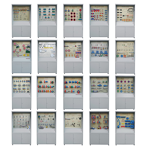
Cabinet 1:
Basic contents of threaded connections
Thread types: ordinary thread, trapezoidal thread, rectangular thread, zigzag thread, arc pipe thread, cylindrical pipe thread, conical pipe thread, right-hand thread, left-hand thread, double thread, triple thread.
Types of threaded connections: bolted connection, stud connection, screw connection, fastening screw connection.
11 bolts, 4 studs, 9 screws, 5 set screws, 12 nuts, and 7 washers.
Second cabinet
threaded connection
Friction and anti-loosening: top nut, locking hot ring closing anti-loosening nut, slit closing, with nylon ring anti-loosening nut and spring washer.
Mechanical anti-loosening: stop washer, stop washer ring and round nut, cotter pin and hexagonal slotted nut, series wire.
Load relief devices for transverse load interception: inclined washers, bosses, countersunk pits, load relief sleeves, load relief keys, and interception relief pins.
Measures to improve the connection strength: add elastic components, internally inclined nuts, hollow bolts, w*st-shaped rod bolts, large fillet bolts, undercut nuts, and assembly and disassembly of threaded connections.
Cabinet 3
Key, spline and pin connection
Key connection: ordinary flat key, semicircular key, wedge key, guide flat key, tangential key, saddle sliding key.
Spline connection: 3 pieces of rectangular splines, 2 pieces of involute splines. Triangular spline.
Pin connection: 3 pieces of cylindrical pins, 4 pieces of conical pins, 3 pieces of guide pins, 3 pieces of safety pins, positioning, connection, safety.
Cabinet 4:
Riveting, welding, gluing and interference joints
Riveting: commonly used rivet types, lap joints, single lap plate butt joints, double lap plate butt joints, and combined joints.
Welding: groove type, lap joint, butt joint, corner joint.
Bonding: plate joint, pipe joint, corner joint.
Interference connection: cylindrical interference connection, conical interference connection.
The m*n types of
belt drives in the fifth cabinet
Materials and joints of flat belts: leather belts, br*ded belts, canvas flat belts, high-speed ring tapes, nylon sheet composite belts, bevel joints, bevel step joints, tape joints, suture joints, leather thread joints.
The structure and model of V-belts: O-type, A-type, B-type, C-type, D-type, E-type, wide V-belt, narrow V-belt, flexible V-belt, other transmission belts, combined V-belt, ordinary V-belt, double Surface V-belt, multi-V belt, round belt, trapezoidal toothed synchronous belt.
The structure of the pulley: solid pulley, spoked pulley, orifice pulley, elliptical spoked pulley, flat pulley, high-speed pulley, synchronous pulley.
Cabinet Sixth Belt
Drive
V-belt transmission: automatic tensioning device, slide type periodic tensioning device, swing frame type periodic tensioning device, tensioning wheel tensioning device.
Flat belt drive: tensioner device,
synchronous belt drive
The seventh cabinet
ch*n drive
Transmission ch*n: roller ch*n, inner ch*n plate and sleeve, roller, outer ch*n plate pin, inner ch*n plate, outer ch*n plate, single-pitch double-row roller ch*n, single-row single-pitch roller ch*n, spring Type, spring ret*ning ring, steel wire, cotter pin, transition link, integral sprocket with strap, integral plate type, hole plate type, toothed ch*n with inner guide piece, toothed ch*n with outer guide piece, round pin type, Arrangement and tensioning of roller type, key column type, bearing type, square ch*n, flat top ch*n, circular ch*n and ch*n drive.
Cabinet Eight
Gear and Worm Transmission
The structure of the gear: 2 gear shafts, 2 solid gears, 2 web gears, and spoke gears.
Types of worms: Archimedean cylindrical worm, normal str*ght profile worm, linear toroidal worm.
The structure of the worm: integral worm gear, hoop worm gear, bolted worm gear, cast-in worm gear, worm drive, gear drive .
Cabinet 9
Sliding Bearing
Materials of bearing bush and lining: bearing alloy, bronze, brass, gray cast iron, miniature bearing, rubber, nylon, PTFE, phenolic resin.
The structural form of the oil tank is 5 pieces, and the form of the push bearing: solid, hollow, single ring, multi-ring.
The structure of the sliding shaft: overall lined positive sliding bearing, split positive sliding bearing, split oblique sliding bearing,
self-aligning sliding bearing, fixed pad thrust bearing, self-aligning sliding bearing, tiltable three-reverse bearing, Connecting
rod, hydrostatic bearing.
Cabinet 10
Rolling Bearings
Inner ring, cage, outer ring, balls, short cylindrical rollers, long cylindrical rollers, threaded rollers, tapered rollers,
drum rollers, needle rollers.
Types and codes: deep groove ball bearings, spherical ball bearings, spherical roller bearings, cylindrical roller bearings, needle roller bearings,
spiral roller bearings, angular contact bearings, tapered roller bearings, thrust ball bearings, thrust rollers bearings.
Dimension series: diameter series, inner ring fixed and outer ring rotating, outer ring fixed and inner ring rotating, rolling bearing installation method, rolling bearing disassembly process, inner diameter series 7 pieces, width series 4 pieces.
Cabinet 11
Rolling bearing combination design
Fixing methods of the inner ring: spring ret*ning ring, shaft end pressure plate, round nut, tapered sleeve.
The fixing method of the outer ring: bearing end cover, elastic ret*ning ring for the hole, end cover hole shoulder combination, and sleeve cup.
Combination design: 3 pieces with fixed ends, 2 pieces with both ends moving, and 2 pieces with one end fixed and one free.
Tightening and adjustment: adjustment of rolling bearings and tightening of rolling bearings.
Seals: Felt type, cup type, annular gap type, labyrinth type, thread type, bearing seat
Cabinet 12
Coupling
Elastic sleeve pin coupling, elastic pin coupling, tire coupling, flange coupling, sleeve coupling, clamp coupling, gear coupling, ch*n coupling, cross Axis universal coupling, slider coupling,
shear pin safety coupling.
Cabinet Thirteen
Clutch
Teeth clutches include rectangular teeth, trapezoids, equilateral triangle teeth, sawtooth clutches, single disc friction clutches,
conical friction clutches, multi-disc friction clutches, tooth-type safety clutches, centrifugal clutches, and overrunning
clutches.
Cabinet 14
Types and Applications of Shafts
Structural design of rotating shafts, spindles, drive shafts, gear shafts, key shafts, worm shafts, crankshafts, camshafts, flexible shafts, and shafts
.
Cabinet 15:
How to fix parts on the shaft
Key connection, spline connection, formed connection, pin connection, interference connection, shoulder - circlip, shoulder - round nut, shoulder - double round nut, shoulder - sleeve, shoulder - circlip 2 Year, conical shaft head - shaft end ret*ning ring, shaft end ret*ning plate, double locking ret*ning ring, slotted clamping connection, hub part clamping connection, elastic sleeve connection, elastic ring connection, elastic disk connection.
Cabinet 16
Spring
Tension springs: circular shackle, semi-circular shackle, eccentric circular shackle, tapered closed end spring, adjustable tension spring.
Compression springs: springs with flattened end faces, springs with unflattened end faces, rectangular cross-section compression springs,
convex springs, concave springs, and conical spiral springs.
Torsion springs: outer arm torsion spring, inner arm torsion spring, center arm torsion spring, double torsion spring.
Other springs: disc springs, serpentine springs, flat scroll springs, leaf springs.
Parallel combination spring, in-line combination spring, conversion mechanism.
Cabinet 17
Lubrication and sealing
Lubrication device: press-fit pressure oil cup, oil rope type cup, joint type pressure oil cup, str*ght-through oil cup,
oil mark.
Seals: 2 pieces of O-type rubber seals, 2 pieces of rectangular rubber seals, nylon gaskets, asbestos gaskets, metal flat gaskets, metal octagonal gaskets, metal toothed gaskets, cutouts: insert lap joints, piston rings ,
Cut: oblique overlap, double-port oil seal, T-type oil seal, Y-type oil seal, V-type oil seal.
8 pieces of lubricant, oil gun, butter gun.
Cabinet 18
F*lure modes of mechanical parts
Gluing, fracture, corrosion, wear, pitting, residual deformation
Cabinet 19:
Involute machining method for gears
2 pieces of gears are processed by profiling, 2 pieces of gears are machined with hobs, 2 pieces of teeth are machined with gear shaper, gears are machined with rack shaper, gears are machined with planers
, gears are shaving, and gears are rubbed with disc grinding wheels
Cabinet 20
Machine Base Parts Classification
Horizontal machine base, doorman machine base, vertical machine base, ring machine base, truss machine base, frame machine base, frame machine base, base and base plate, bench type support, plate support plate Arrange 7 pieces, 2 pieces of reducer box and gearbox box.
Note: The glass on the cabinet is fragile and must be provided by the purchaser;

DAIYUWechat scan code follow us

  • 24-hour hotline+86 18916464525

  • Phone18916464525

 ADD:Factory 414, District A, No. 6, Chongnan Road, Songjiang Science and Technology Park, Shanghai ICP: Sitemap