Shanghai Daiyu Education Equipment Manufacturing Co., Ltd.
Language:


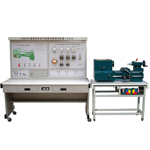


The ordinary lathe electrical skills tr*ning device (semi-physical) adds the C6140 ordinary lathe simulation semi-physical model , which connects the electrical part of the machine tool and the physical model of the machine tool through the interface, showing all the motion processes of the machine tool, making it more realistic and intuitive.
2. Structural requirements
1. The semi-physical simulation model of the C6140 ordinary lathe is a design that refers to the functions of the actual C6140 ordinary lathe and is scaled down according to a cert*n size ratio;
2. The operation of the electrical part of this device can realize various movements of the C6140 ordinary lathe, including: spindle forward and reverse rotation, table feeding and other movements;
3. All electrical contacts of the machine tool are equipped with troubleshooting switches on the panel of the device;
4. Through fault setting, students can truly understand the connection between the fault point and the actual lathe, so that students can master the practical ability of actual electrical circuit rep*r and m*ntenance;
5. All fault point settings are behind the control panel, with the operating surface and electrical components on the front.
3. Practical tr*ning project requirements
1. Be familiar with the mechanism and principles of commonly used low-voltage electrical appliances;
2. Circuit line analysis;
3. Understand the actual movement of the machine tool by observing the movement of the machine tool model;
4. Find the fault point in the line through measurement and troubleshoot the lathe;
5. Set up fault points as a skill assessment device for m*ntenance electricians .
Fault settings:
6. The power indicator does not light up;
7. Spindle motor M1 cannot start;
8. Cooling pump motor M2 cannot start;
9. The control circuit is disconnected;
10. Spindle motor M1 cannot run continuously;
11. Power phase f*lure;
12. The thermal relay FR1 contact is disconnected;
13. The thermal relay FR2 contact is disconnected;
14. The fuse is blown;
15. The light does not come on.
No less than 20 faults can be set, and all fault points are implemented in hardware.
4. Technical parameters
1. Input power: three-phase four-wire (380V; 50Hz);
2. Working environment: temperature -10℃~+40℃;
3. Device capacity: <1kVA;
4. Device weight: <150kg;
5. The semi-physical model and the physical model are reduced in a cert*n proportion to facilitate intuitive teaching and enable various movements of the lathe.
5. Technical performance index requirements
The practical tr*ning device consists of an electrical control panel and a semi-physical model.
(1) Electrical control panel
The tr*ning device m*nly consists of a control panel and a tr*ning table. The control panel is made of iron double-layer matt dense texture spray-plastic structure, 4mm high-strength insulated panel, and the panel adopts wire mesh technology, which is strong and beautiful. The lathe schematic diagram panel and the electrical circuit component wiring area panel are fixed on the control screen, and the lower layer is equipped with components such as the AC power supply control panel. The tr*ning table is made of iron with a double-layer matte dense spray-p*nted structure. The table top is made of fireproof, waterproof and wear-resistant high-density board. It has a solid structure and beautiful appearance.
(2) Personal and equipment safety protection requirements
Equipped with current leakage circuit breaker to ensure the safety of people and experimental equipment.
It is equipped with a voltage-type leakage protection function to avoid leakage on the surface of the experimental device and protect the personal safety of the experimenter.
(3) Technical description of AC power supply
1. Power control board: Three-phase four-wire 380V power input, through the leakage protector, turn on the m*n switch, and controlled by the contactor through the start and stop buttons. The emergency stop button is used as the m*n power source for emergency stop.
2. C6140 lathe diagram: Printed with C6140 lathe three-dimensional schematic diagram and electrical control schematic diagram.
3. Lathe electrical circuit component wiring area: circuit breakers, fuses, contactors, thermal relays, transformers, rectifier bridges and all major machine tool electrical appliances are installed. These components are installed directly on the panel, and their functions can be clearly seen. Action status
4. Troubleshooting device: There are multiple micro buttons on the panel, each micro button corresponds to a fault point. After students determine the fault point based on the fault phenomenon, they can press the corresponding micro button to perform troubleshooting operations, which is simple and convenient. .
(4) C6140 ordinary lathe simulation semi-physical model
The simulated semi-physical lathe of the C6140 ordinary lathe is made of castings. The special mold is formed in one go. The semi-physical model is close to the real machine tool. The voltage level of the motor used in the model is exactly the same as that of the actual machine tool. It can truly demonstrate the various operating states of the C6140 ordinary lathe.
Lathe model technical parameters
1. Spindle motor power:  (Figure 1)") 0.5 (kW), the spindle speed can be adjusted;
0.5 (kW), the spindle speed can be adjusted;
2. Machine tool overall dimensions: (length × width × height) mm: 600 × 300 × 280 (reference);
3. The semi-physical model and the physical model are reduced in a cert*n proportion to facilitate intuitive teaching and enable various movements of the lathe.
(5) Electrical control function
The functions completed by the electrical control circuit should be consistent with the actual C6140 ordinary lathe control, including electric drive, m*n circuit and control circuit or auxiliary circuit, etc.
All electrical components should use nationally certified products. Ensure product quality.
(6) Virtual simulation system
1. M*ntenance of electricians, electronic motors and vocational qualification tr*ning assessment simulation software
This software is in apk format and can be used on PC or mobile. This software can set faults manually or automatically. This software can manually set fault points through the green box in the circuit diagram (you can set up to 39 fault points), you can also automatically set one random fault point, two random fault points, three random fault points, four random fault points, and five random fault points through the system. It has functions such as toolbox, component library, magnifying glass, circuit diagram, etc. You can choose a multimeter for testing through the toolbox, select appropriate components through the component library, and clearly understand each component and circuit through the magnifying glass. This software allows students to understand the working principle and circuit structure of the motor star-delta start control circuit through the setting of faults in the motor star-delta start control circuit and various investigations.
2. Virtual spectrum analyzer, logic analyzer, oscilloscope, and three-meter simulation software:
This software is in apk format and can be used on PC or mobile terminals. The functions of this software are: resistance measurement, AC voltage measurement (measuring transformer, if the multimeter burns out when measuring the transformer, black smoke will emit prompts and can reset the multimeter), determine the polarity of the transistor, measure the DC voltage (the light turns on when the ammeter is turned on), measure the DC current, and determine the quality of the capacitor. This software can drag the red and black pen tips at will. When the two pen tips are dragged and positioned on the object to be measured, a red circle will be displayed. If the positioning is not accurate, no red circle will be displayed, and when incorrect operations are performed (such as the wrong range selected, If the measured data is wrong, etc.), the meter pointer will be unresponsive, prompting errors and re-measurement, etc. This multimeter can select AC voltage range, DC voltage range, resistance range, current range, resistance adjustment to 0, and can enlarge the display data. Clearly view the measured data size. Students can learn the correct use of multimeters through this software.
3. Microcontroller and plc programmable design and control virtual simulation software:
This software is developed based on unity3d and has built-in experimental steps, experimental instructions, circuit diagrams, component lists, connection lines, power on, circuit diagrams, scene reset, return and other buttons. After the connections and codes are correct, you can start/stop, The forward movement and reverse movement buttons operate the 3D machine tool model to move. In the connected line state, the 3D machine tool model can be enlarged/reduced and translated.
1. Relay control: Read the experiment instructions and enter the experiment. By reading the circuit diagram, select the relays, thermal relays, switches and other components in the component list and drag and drop them into the electrical cabinet. The limiters are placed in the three-dimensional On the machine tool model, you can choose to cover it, and some component names can be renamed. Then click the Connect Line button to connect terminals to terminals. After successfully connecting the machine tool circuit, choose to turn on the power and proceed. If the component or line An error box will pop up if there is a connection error, and the scene can be reset at any time.
2. PLC control: The experiment is the same as relay control, with the addition of PLC control function. After the connection is completed, enter the program writing interface through the PLC encoding button, and write two programs, forward and reverse, with a total of 12 ladder diagram symbols. The writing is completed. Finally, select Submit for program verification. After the verification is successful, turn on the power for operation. Error boxes will pop up for component, line connection, and code errors, and the scene can be reset at any time.
3. Single-chip microcomputer control: The experiment is the same as relay control, with the addition of single-chip microcomputer control function. After the connection is completed, enter the programming interface through the C coding button, enter the correct C language code, and after successful submission and verification, turn on the power for operation, components, lines If there are connection or code errors, an error box will pop up, and the scene can be reset at any time.
Popular products: Electrician tr*ning bench
 Wechat scan code follow us

24-hour hotline+86 18916464525

Phone18916464525
ADD:Factory 414, District A, No. 6, Chongnan Road, Songjiang Science and Technology Park, Shanghai ICP: Sitemap