Shanghai Daiyu Education Equipment Manufacturing Co., Ltd.
Language:


1. Functional features
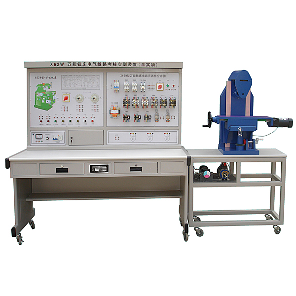
1. The semi-physical simulation model of the X62W universal milling machine is designed to be reduced in a cert*n proportion with reference to the size of the actual X62W universal milling machine;
2. The operation of the electrical part of this device can realize various movements of the X62W universal milling machine, including: spindle forward and reverse rotation, worktable longitudinal feed, worktable vertical feed and cooling pump operation, and limit protection of extreme positions. ;
3. All contacts of the machine tool’s electrical circuits have corresponding test points on the panel of the device to facilitate students to detect faults;
4. The voltage levels of all motors on the semi-physical model are exactly the same as those of the actual machine tools;
5. The bed of the semi-physical machine tool is made of castings, and the special mold is formed in one go. Ball screw drive, handwheel uses actual machine tool parts, close to the real machine tool;
6. Each component of the semi-physical machine tool is in different colors, making it easier for students to understand and accept during tr*ning;
7. The surface of the movable guide r*l of the semi-physical machine tool adopts high-frequency quenching process, which is durable;
8. There are 32 switches in the fault box of the control panel. The corresponding fault point can be set by flipping the fault switch.
2. Technical performance
1. Input power supply: three-phase four-wire (~380V±10% 50Hz)
2. Working environment: temperature -10℃~+40℃, relative humidity <85% (25℃), altitude <4000m
3. Device capacity: <1KVA
4. Overall dimensions: 1410mm×725mm×1535mm
3. Basic equipment of the device
1. Power control panel
(1) AC power supply (with leakage protection measures)
Provide three-phase AC power (380V)
(2) Personal safety protection system
The screen is equipped with a voltage-type leakage protection device. If there is leakage in the control screen or in the strong current output, an alarm will be issued and the power will be cut off to ensure the safety of the experimental process.
A set of current-type leakage protectors is installed on the screen. If there is leakage in the control panel and the leakage current exceeds a cert*n value, the power supply will be cut off.
2. Master control and graphic display board
All m*n electrical appliances and action indicator lights of the machine tool are installed on the panel. All operations of the machine tool are performed on this panel. The indicator lights can indicate the corresponding actions of the machine tool.
There is a three-dimensional diagram of the X62W universal milling machine printed on the panel, and you can intuitively see the outline of the X62W universal milling machine.
3. Component mounting plate
The panel is equipped with circuit breakers, fuses, contactors, thermal relays, transformers and other components. These components are directly installed on the surface of the panel, and their actions can be viewed intuitively.
4. Faulty switch box.
There are 32 switches, of which 1 to 29 are used for fault settings; three switches 30 to 32 are reserved.
5. Experiment table
The experimental table is made of iron with a double-layer matt dense spray-p*nted structure. The table top is made of fireproof, waterproof and wear-resistant high-density board. It has a solid structure and is shaped like a rectangular parallelepiped structure. It has a beautiful and elegant shape. It is equipped with two large drawers for placing tools. and information, etc. The desktop is used to install the power control panel and provide a spacious and comfortable work surface. The bottom of the experimental table is also equipped with four directional wheels and four fixed adjustment mechanisms, which are convenient for movement and fixation and are conducive to laboratory layout.
6. Semi-physical model table size: 1268mm × 723mm × 798mm
7. X62W universal milling machine model size: 700mm × 550mm × 550mm
8. Longitudinal movement stroke of worktable: 130mm
9. Worktable vertical movement stroke: 30 mm
10. Lateral movement stroke of the workbench: 50 mm
11. Virtual simulation system
1. M*ntenance of electricians, electronic motors and vocational qualification tr*ning assessment simulation software
This software is in apk format and can be used on PC or mobile. This software can set faults manually or automatically. This software can manually set fault points through the green box in the circuit diagram (you can set up to 39 fault points), you can also automatically set one random fault point, two random fault points, three random fault points, four random fault points, and five random fault points through the system. It has functions such as toolbox, component library, magnifying glass, circuit diagram, etc. You can choose a multimeter for testing through the toolbox, select appropriate components through the component library, and clearly understand each component and circuit through the magnifying glass. This software allows students to understand the working principle and circuit structure of the motor star-delta start control circuit through the setting of faults in the motor star-delta start control circuit and various investigations.
2. Virtual spectrum analyzer, logic analyzer, oscilloscope, and three-meter simulation software:
This software is in apk format and can be used on PC or mobile terminals. The functions of this software are: resistance measurement, AC voltage measurement (measuring transformer, if the multimeter burns out when measuring the transformer, black smoke will emit prompts and can reset the multimeter), determine the polarity of the transistor, measure the DC voltage (the light turns on when the ammeter is turned on), measure the DC current, and determine the quality of the capacitor. This software can drag the red and black pen tips at will. When the two pen tips are dragged and positioned on the object to be measured, a red circle will be displayed. If the positioning is not accurate, no red circle will be displayed, and when incorrect operations are performed (such as the wrong range selected, If the measured data is wrong, etc.), the meter pointer will be unresponsive, prompting errors and re-measurement, etc. This multimeter can select AC voltage range, DC voltage range, resistance range, current range, resistance adjustment to 0, and can enlarge the display data. Clearly view the measured data size. Students can learn the correct use of multimeters through this software.
3. Microcontroller and plc programmable design and control virtual simulation software:
This software is developed based on unity3d and has built-in experimental steps, experimental instructions, circuit diagrams, component lists, connection lines, power on, circuit diagrams, scene reset, return and other buttons. After the connections and codes are correct, you can start/stop, The forward movement and reverse movement buttons operate the 3D machine tool model to move. In the connected line state, the 3D machine tool model can be enlarged/reduced and translated.
1. Relay control: Read the experiment instructions and enter the experiment. By reading the circuit diagram, select the relays, thermal relays, switches and other components in the component list and drag and drop them into the electrical cabinet. The limiters are placed in the three-dimensional On the machine tool model, you can choose to cover it, and some component names can be renamed. Then click the Connect Line button to connect terminals to terminals. After successfully connecting the machine tool circuit, choose to turn on the power and proceed. If the component or line An error box will pop up if there is a connection error, and the scene can be reset at any time.
2. PLC control: The experiment is the same as relay control, with the addition of PLC control function. After the connection is completed, enter the program writing interface through the PLC encoding button, and write two programs, forward and reverse, with a total of 12 ladder diagram symbols. The writing is completed. Finally, select Submit for program verification. After the verification is successful, turn on the power for operation. Error boxes will pop up for component, line connection, and code errors, and the scene can be reset at any time.
3. Single-chip microcomputer control: The experiment is the same as relay control, with the addition of single-chip microcomputer control function. After the connection is completed, enter the programming interface through the C coding button, enter the correct C language code, and after successful submission and verification, turn on the power for operation, components, lines If there are connection or code errors, an error box will pop up, and the scene can be reset at any time.
4. Equipment configuration
|
serial number |
name |
quantity |
Remark |
|
1 |
ZRJC-X62W universal milling machine electrical skills tr*ning and assessment device |
1 set |
|
|
2 |
Semi-physical model of X62W universal milling machine (including tr*ning table) |
1 set |
Equipped with connection interface to the electrical part, connected via cable |
4. Practical tr*ning projects and purposes
1. Familiar with the mechanism and principles of commonly used low-voltage electrical appliances
2. Understand the actual movement of the machine tool by observing the movement of the machine tool model
3. Understand the principles of machine tool electrical control and various protection devices
4. Master the troubleshooting methods of common faults in machine tools
5. List of fault point settings
|
serial number |
Fault phenomenon |
serial number |
Fault phenomenon |
|
1 |
Cooling pump motor cannot start |
16 |
The feed motor cannot rotate forward |
|
2 |
Neither the spindle nor the feed can be started. |
17 |
The workbench cannot be fed upward or backward |
|
3 |
Spindle has no impulse to change speed |
18 |
Round workbench not working |
|
4 |
The spindle stops and brakes abnormally |
19 |
Round workbench not working |
|
5 |
Spindle motor cannot start |
20 |
Non-circular worktable cannot feed to the right |
|
6 |
The spindle stops and cannot be braked |
twenty one |
Non-circular items cannot be fed up and down (or front and back) or fast forwarded. |
|
7 |
The spindle cannot be started |
twenty two |
Cannot feed up and down (or front and back) |
|
8 |
Feed motor cannot start |
twenty three |
Cannot feed downward (or forward) |
|
9 |
Feed motor cannot start |
twenty four |
The feed motor cannot be reversed |
|
10 |
Feed motor cannot start |
25 |
Can only fast forward in one place |
|
11 |
There is no impulse in the feed speed change, and the circular worktable cannot work. |
26 |
Can only fast forward in one place |
|
12 |
The workbench cannot be fed left or right |
27 |
Can't fast forward |
|
13 |
The workbench cannot be fed left or right |
28 |
Solenoid valve does not operate |
|
14 |
Non-round worktable does not work |
29 |
Feed motor does not rotate |
|
15 |
The workbench cannot feed to the left |
Hot-selling product: Electrician tr*ning bench
 Wechat scan code follow us

24-hour hotline+86 18916464525

Phone18916464525
ADD:Factory 414, District A, No. 6, Chongnan Road, Songjiang Science and Technology Park, Shanghai ICP: Sitemap