Shanghai Daiyu Education Equipment Manufacturing Co., Ltd.
Language:


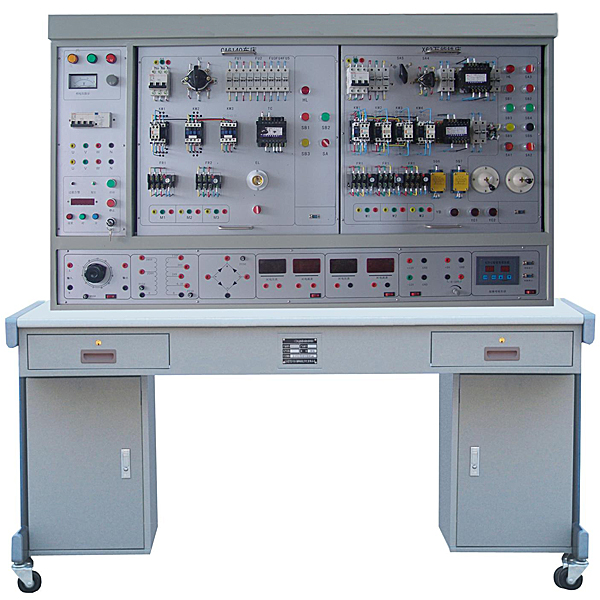


This device is a practical tr*ning equipment developed by our company for the teaching and assessment of electrical control in electrical , automation and related majors in various vocational and technical colleges , social electrician tr*ning, and various county and city m*ntenance electrician appr*sal institutes (stations). It is fully used for classroom demonstrations, machine tool electrical control principle operations and practical tr*ning and internship assessments. The device can separately assess seven types of machine tool circuits by easily replacing the hanging boxes, with high utilization rate and reduced capital investment. Each hanging box is equipped with an independent fault setting box, which is easy to operate. Since the equipment uses common electrical appliances in industry, it can be used as assessment equipment for electrical vocational tr*ning. The tr*ning in this setting can improve students' practical ability and troubleshooting skills, and overcome the shortcomings of previous teaching on actual equipment that is expensive and difficult to achieve the teaching purpose.
2. Scope of application
By replacing the hanging box, the practical tr*ning and assessment of the following seven types of machine tool circuits can be completed:
1. Z35 radial drilling machine electrical skills tr*ning and assessment
2. M7120 surface grinder circuit skills tr*ning and assessment
3. Z3050 radial drilling machine circuit skills tr*ning assessment
4. CA6140 ordinary lathe circuit skills tr*ning and assessment
5. M1432 grinder circuit skills tr*ning and assessment
6. X62W universal milling machine circuit skills tr*ning and assessment
7. T68 boring machine circuit skills tr*ning and assessment
Each circuit is equipped with 16 fault points, and the fault points are randomly designed through the fault setting box on the hanging box.
3. Characteristics
1. One device can complete the practical tr*ning and assessment of seven types of machine tool circuits, with significant economic benefits.
2. It is equipped with voltage type and current type protectors to ensure the personal safety of the operator. It is also equipped with an experiment manager that can set the tr*ning time, alarm regularly and cut off the power supply. Provide a unified standard for student assessment.
3. It is equipped with a single-chip microcomputer and full-process monitoring of the three-phase output working power supply to detect overload or short circuit between phases and lines. Once it occurs, the power supply will be cut off and an alarm will be issued. After troubleshooting, the reset button can be pressed to restart the power supply to ensure the safety of the equipment.
4. Technical performance
1. Input power: three-phase four-wire ~ 380V ±10% 50Hz
2. Temperature: -5℃~+40℃, relative humidity <85% (25℃)
3. Device capacity: <1.5KVA
4. Overall dimensions: 1500mm×750mm×1400mm
5. Structure and functions of the device
The device m*nly consists of a tr*ning screen, a tr*ning machine tool circuit hanging box, and a tr*ning table.
(1) Practical tr*ning screen
The tr*ning screen is an iron double-layer matt dense textured spray-plastic structure with an aluminum alloy panel.
1. M*n control function board
(1) Three-phase four-wire power input, the m*n switch is connected through the leakage protector, and the contactor is operated through the start and stop buttons.
(2) There are three 450V pointer AC voltmeters to indicate the three-phase power supply voltage of the power input, and three indicator lights to indicate the connection between the tr*ning platform and the external power supply.
(3) Three-phase four-wire power output, with a single-chip microcomputer that monitors the entire phase, automatically cuts off the m*n power supply due to overload or short circuit between phases, and is equipped with alarm and reset functions.
(4) Experiment manager: It has the functions of setting tr*ning time, timing alarm, cutting off power, etc.
(5) Equipped with 380V and 220V sockets to provide working power for external instruments.
2. Auxiliary device installation screen
The installation screen on the right is equipped with a demonstration and verification motor for practical tr*ning and assessment . All the wiring ports of the motor have been led to the panel and are connected to the practical tr*ning and assessment circuit hanging box through special safety wires.
3. Virtual simulation system
1. M*ntenance of electricians, electronic motors and vocational qualification tr*ning assessment simulation software
This software is in apk format and can be used on PC or mobile. This software can set faults manually or automatically. This software can manually set fault points through the green box in the circuit diagram (you can set up to 39 fault points), you can also automatically set one random fault point, two random fault points, three random fault points, four random fault points, and five random fault points through the system. It has functions such as toolbox, component library, magnifying glass, circuit diagram, etc. You can choose a multimeter for testing through the toolbox, select appropriate components through the component library, and clearly understand each component and circuit through the magnifying glass. This software allows students to understand the working principle and circuit structure of the motor star-delta start control circuit through the setting of faults in the motor star-delta start control circuit and various investigations.
2. Virtual spectrum analyzer, logic analyzer, oscilloscope, and three-meter simulation software:
This software is in apk format and can be used on PC or mobile terminals. The functions of this software are: resistance measurement, AC voltage measurement (measuring transformer, if the multimeter burns out when measuring the transformer, black smoke will emit prompts and can reset the multimeter), determine the polarity of the transistor, measure the DC voltage (the light turns on when the ammeter is turned on), measure the DC current, and determine the quality of the capacitor. This software can drag the red and black pen tips at will. When the two pen tips are dragged and positioned on the object to be measured, a red circle will be displayed. If the positioning is not accurate, no red circle will be displayed, and when incorrect operations are performed (such as the wrong range selected, If the measured data is wrong, etc.), the meter pointer will be unresponsive, prompting errors and re-measurement, etc. This multimeter can select AC voltage range, DC voltage range, resistance range, current range, resistance adjustment to 0, and can enlarge the display data. Clearly view the measured data size. Students can learn the correct use of multimeters through this software.
3. Microcontroller and plc programmable design and control virtual simulation software:
This software is developed based on unity3d and has built-in experimental steps, experimental instructions, circuit diagrams, component lists, connection lines, power on, circuit diagrams, scene reset, return and other buttons. After the connections and codes are correct, you can start/stop, The forward movement and reverse movement buttons operate the 3D machine tool model to move. In the connected line state, the 3D machine tool model can be enlarged/reduced and translated.
1. Relay control: Read the experiment instructions and enter the experiment. By reading the circuit diagram, select the relays, thermal relays, switches and other components in the component list and drag and drop them into the electrical cabinet. The limiters are placed in the three-dimensional On the machine tool model, you can choose to cover it, and some component names can be renamed. Then click the Connect Line button to connect terminals to terminals. After successfully connecting the machine tool circuit, choose to turn on the power and proceed. If the component or line An error box will pop up if there is a connection error, and the scene can be reset at any time.
2. PLC control: The experiment is the same as relay control, with the addition of PLC control function. After the connection is completed, enter the program writing interface through the PLC coding button, and write two programs, forward and reverse, with a total of 12 ladder diagram symbols. The writing is completed. Finally, select Submit for program verification. After the verification is successful, turn on the power for operation. Error boxes will pop up for component, line connection, and code errors, and the scene can be reset at any time.
3. Single-chip microcomputer control: The experiment is the same as relay control, with the addition of single-chip microcomputer control function. After the connection is completed, enter the programming interface through the C coding button, enter the correct C language code, and after successful submission and verification, turn on the power for operation, components, lines If there are connection or code errors, an error box will pop up, and the scene can be reset at any time.
6. Configuration list
|
serial number |
name |
unit |
quantity |
|
1 |
Tr*ning control panel (including motor) |
tower |
1 |
|
2 |
Tr*ning table |
tower |
1 |
|
3 |
Z35 radial drilling machine electrical skills tr*ning assessment hanging box |
set |
1 |
|
4 |
M7120 surface grinder circuit skills tr*ning assessment hanging box |
set |
1 |
|
5 |
Z3050 radial drilling machine circuit skills tr*ning assessment hanging box |
set |
1 |
|
6 |
CA6140 ordinary lathe circuit skills tr*ning assessment hanging box |
set |
1 |
|
7 |
M1432 grinder circuit skills tr*ning assessment hanging box |
set |
1 |
|
8 |
X62W universal milling machine circuit skills tr*ning assessment hanging box |
set |
1 |
|
9 |
T68 boring machine circuit skills tr*ning assessment hanging box |
set |
1 |
|
10 |
Experimental wire |
strip |
several |
(1) List of fault point settings for X62W universal milling machine circuit skills tr*ning and assessment device:
|
serial number |
Fault phenomenon |
serial number |
Fault phenomenon |
|
1 |
Cooling pump cannot start |
13 |
The feed motor cannot rotate forward |
|
2 |
Neither the spindle nor the feed can be started. |
14 |
The workbench cannot be fed upward or backward |
|
3 |
Spindle has no impulse to change speed |
15 |
Round workbench not working |
|
4 |
The spindle stops and brakes abnormally |
16 |
Non-circular worktable cannot feed to the right |
|
5 |
Spindle motor cannot start |
17 |
Non-circular items cannot be fed up and down (or front and back) or fast forwarded. |
|
6 |
The spindle stops and cannot be braked |
18 |
Cannot feed up and down (or front and back) |
|
7 |
The spindle cannot be started |
19 |
Cannot feed downward (or forward) |
|
8 |
Feed motor cannot start |
20 |
The feed motor cannot be reversed |
|
9 |
There is no impulse in the feed speed change, and the circular worktable cannot work. |
twenty one |
Can only fast forward in one place |
|
10 |
The workbench cannot be fed left or right |
twenty two |
Can't fast forward |
|
11 |
Non-round worktable does not work |
twenty three |
Solenoid valve does not operate |
|
12 |
The workbench cannot feed to the left |
twenty four |
Feed motor does not rotate |
(2) List of fault point settings for T68 horizontal boring machine circuit skills tr*ning and assessment hanging box:
|
serial number |
Fault phenomenon |
serial number |
Fault phenomenon |
|
1 |
The machine cannot be started |
14 |
Spindle motor cannot rotate forward |
|
2 |
Spindle forward rotation cannot be started |
15 |
The spindle only has jog control |
|
3 |
Spindle forward rotation cannot be started |
16 |
Spindle motor cannot rotate forward |
|
4 |
Spindle forward rotation cannot be started |
17 |
The spindle motor cannot reverse |
|
5 |
Spindle forward rotation cannot be started |
18 |
Spindle forward rotation is not working properly |
|
6 |
Spindle forward rotation cannot be started |
19 |
The spindle cannot work at low speed |
|
7 |
Spindle forward rotation cannot be started |
20 |
Spindle reversal is not working properly |
|
8 |
Spindle forward rotation cannot be started |
twenty one |
Spindle does not work at high speed |
|
9 |
Spindle cannot work |
twenty two |
Fast motor cannot rotate forward |
|
10 |
Spindle no high speed |
twenty three |
Fast motor cannot rotate forward |
|
11 |
Spindle stops without braking |
twenty four |
Fast motor cannot reverse |
|
12 |
Spindle speed change without impulse |
25 |
Fast motor does not rotate |
|
13 |
Shift impulse not working properly |
(3) List of fault point settings for Z3040 radial drilling machine circuit skills tr*ning and assessment device:
|
serial number |
Fault phenomenon |
serial number |
Fault phenomenon |
|
1 |
The machine tool is not working |
11 |
The pillar cannot be loosened |
|
2 |
The machine tool is not working |
12 |
The pillar cannot be loosened |
|
3 |
Spindle motor cannot start |
13 |
Spindle box cannot stay loose |
|
4 |
Spindle motor cannot start |
14 |
The spindle box cannot be loosened |
|
5 |
The rocker arm cannot rise |
15 |
The machine cannot be started |
|
6 |
The rocker arm cannot rise |
16 |
Cooling pump cannot start |
|
7 |
The rocker arm cannot be lowered |
17 |
The lighting is not on |
|
8 |
The rocker arm cannot be lowered |
18 |
Spindle does not work |
|
9 |
The column cannot be clamped |
19 |
Column clamping motor does not work |
|
10 |
The column cannot be clamped |
20 |
The rocker arm cannot be r*sed or lowered |
(4) CA6140 ordinary lathe circuit skills tr*ning assessment hanging box fault point setting list:
|
serial number |
Fault phenomenon |
serial number |
Fault phenomenon |
|
1 |
The machine cannot be started |
10 |
Spindle and cooling pump motor cannot start |
|
2 |
The machine cannot be started |
11 |
Cooling pump cannot start |
|
3 |
The machine cannot be started |
12 |
Cooling pump cannot start |
|
4 |
The lighting is not on |
13 |
Cooling pump cannot start |
|
5 |
The machine cannot be started |
14 |
The tool holder cannot move quickly |
|
6 |
The machine cannot be started |
15 |
Spindle does not work |
|
7 |
Spindle and cooling pump motor cannot start |
16 |
Cooling pump not working |
|
8 |
Spindle motor control cannot self-lock |
17 |
Can't move quickly |
|
9 |
Spindle motor control cannot self-lock |
Hot-selling product: Electrician tr*ning bench
Optional machine tool circuit hanging box:
|
serial number |
Unit hanging board |
Unit hanging board function description |
|
1 |
C650-2 ordinary lathe electrical control circuit |
Let students master the electrical working principle of C650-2 lathe and its troubleshooting skills. |
|
2 |
M7120 surface grinder electrical control circuit |
Let students master the electrical working principle of the M71200 lathe and its troubleshooting skills. |
|
3 |
M7130K surface grinder electrical control circuit |
Let students master the electrical working principle of the M7130 lathe and its troubleshooting skills. |
|
4 |
M1432A universal cylindrical grinder electrical control circuit |
Let students master the electrical working principle of the M1432A lathe and its troubleshooting skills. |
|
5 |
Z3050 radial drilling machine electrical control circuit |
Let students master the electrical working principle of Z3050 lathe and its troubleshooting skills. |
|
6 |
Z35 radial drilling machine electrical control circuit |
Let students master the electrical working principle of Z35 lathe and its troubleshooting skills. |
|
7 |
CA6140 lathe circuit intelligent tr*ning and assessment hanging board |
Let students master the electrical working principle of the CA6140 lathe and its troubleshooting skills. |
|
8 |
X62W milling machine circuit intelligent tr*ning assessment hanging board |
Let students master the electrical working principle of the X62W milling machine and its troubleshooting skills. |
|
9 |
T68 boring machine circuit intelligent tr*ning and assessment hanging board |
Let students master the electrical working principle of T68 boring machine and its troubleshooting skills. |
|
10 |
Electric hoist circuit intelligent tr*ning and assessment hanging board |
Let students master the electrical working principles of electric hoists and their troubleshooting skills. |
|
11 |
Z3040B radial drilling machine electrical control circuit |
Let students master the electrical working principle of Z3040B lathe and its troubleshooting skills. |
 Wechat scan code follow us

24-hour hotline+86 18916464525

Phone18916464525
ADD:Factory 414, District A, No. 6, Chongnan Road, Songjiang Science and Technology Park, Shanghai ICP: Sitemap