Shanghai Daiyu Education Equipment Manufacturing Co., Ltd.
Language:


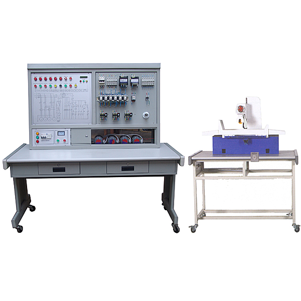


1. Functional features
1. The semi-physical simulation model of the M7120 grinder is a design reduced by a cert*n proportion with reference to the size of the actual M7120 surface grinder;
2. The operation of the electrical part of this device can realize various motion controls of the M7120 surface grinder, including: starting and stopping of the grinding wheel, reciprocating movement of the workbench, lifting movement of the grinding wheel frame, starting and stopping of the cooling pump, and limiting the extreme position. Protect;
3. All contacts of the machine tool’s electrical circuits have corresponding test points on the panel of the device to facilitate students to detect faults;
4. The voltage levels of all motors on the semi-physical model are exactly the same as those of the actual machine tools;
5. The bed of the semi-physical machine tool is made of castings, and the special mold is formed in one go. Ball screw drive, handwheel uses actual machine tool parts, close to the real machine tool;
6. Each component of the semi-physical machine tool is in different colors, making it easier for students to understand and accept during tr*ning;
7. The surface of the movable guide r*l of the semi-physical machine tool adopts high-frequency quenching process, which is durable;
8. There are 32 switches in the fault box of the control panel. By flipping the fault switch, the corresponding fault point can be set.
2. Technical performance
1. Input power: three-phase four-wire (380V±10% 50Hz)
2. Working environment: temperature -10℃ ~ +40℃, relative humidity <85% (25℃), altitude <4000m
3. Device capacity: < 0.2kVA
4. Leakage protection action current: ≤30mA; leakage protection action time: ≤0, 1s
5. Control screen size: 1410mm × 725mm × 1535mm
6. Semi-physical model table size: 1268mm × 723mm × 798mm
7. M7120 grinder model size: 800mm × 400mm × 200mm
8. Worktable moving stroke: 400mm
9. Grinding wheel frame lifting stroke: 100mm
10. Telescopic stroke of grinding head seat: 100mm
11. Virtual simulation system
1. M*ntenance of electricians, electronic motors and vocational qualification tr*ning assessment simulation software
This software is in apk format and can be used on PC or mobile. This software can set faults manually or automatically. This software can manually set fault points through the green box in the circuit diagram (you can set up to 39 fault points), you can also automatically set one random fault point, two random fault points, three random fault points, four random fault points, and five random fault points through the system. It has functions such as toolbox, component library, magnifying glass, circuit diagram, etc. You can choose a multimeter for testing through the toolbox, select appropriate components through the component library, and clearly understand each component and circuit through the magnifying glass. This software allows students to understand the working principle and circuit structure of the motor star-delta start control circuit through the setting of faults in the motor star-delta start control circuit and various investigations.
2. Virtual spectrum analyzer, logic analyzer, oscilloscope, and three-meter simulation software:
This software is in apk format and can be used on PC or mobile terminals. The functions of this software are: resistance measurement, AC voltage measurement (measuring transformer, if the multimeter burns out when measuring the transformer, black smoke will emit prompts and can reset the multimeter), determine the polarity of the transistor, measure the DC voltage (the light turns on when the ammeter is turned on), measure the DC current, and determine the quality of the capacitor. This software can drag the red and black pen tips at will. When the two pen tips are dragged and positioned on the object to be measured, a red circle will be displayed. If the positioning is not accurate, no red circle will be displayed, and when incorrect operations are performed (such as the wrong range selected, If the measured data is wrong, etc.), the meter pointer will be unresponsive, prompting errors and re-measurement, etc. This multimeter can select AC voltage range, DC voltage range, resistance range, current range, resistance adjustment to 0, and can enlarge the display data. Clearly view the measured data size. Students can learn the correct use of multimeters through this software.
3. Microcontroller and plc programmable design and control virtual simulation software:
This software is developed based on unity3d and has built-in experimental steps, experimental instructions, circuit diagrams, component lists, connection lines, power on, circuit diagrams, scene reset, return and other buttons. After the connections and codes are correct, you can start/stop, The forward movement and reverse movement buttons operate the 3D machine tool model to move. In the connected line state, the 3D machine tool model can be enlarged/reduced and translated.
1. Relay control: Read the experiment instructions and enter the experiment. By reading the circuit diagram, select the relays, thermal relays, switches and other components in the component list and drag and drop them into the electrical cabinet. The limiters are placed in the three-dimensional On the machine tool model, you can choose to cover it, and some component names can be renamed. Then click the Connect Line button to connect terminals to terminals. After successfully connecting the machine tool circuit, choose to turn on the power and proceed. If the component or line An error box will pop up if there is a connection error, and the scene can be reset at any time.
2. PLC control: The experiment is the same as relay control, with the addition of PLC control function. After the connection is completed, enter the program writing interface through the PLC encoding button, and write two programs, forward and reverse, with a total of 12 ladder diagram symbols. The writing is completed. Finally, select Submit for program verification. After the verification is successful, turn on the power for operation. Error boxes will pop up for component, line connection, and code errors, and the scene can be reset at any time.
3. Single-chip microcomputer control: The experiment is the same as relay control, with the addition of single-chip microcomputer control function. After the connection is completed, enter the programming interface through the C coding button, enter the correct C language code, and after successful submission and verification, turn on the power for operation, components, lines If there are connection or code errors, an error box will pop up, and the scene can be reset at any time.
3. Intelligent network-based examination system
This device adopts advanced computer communication management technology, complete software, and is easy to operate.
The interface is integrated with student smart digital display clickers. Realize multimedia management teaching, which is set and managed uniformly by the teacher's computer. The student terminal is composed of an LCD screen and an input keyboard, which can display text information on fault points such as test questions and test content in real time. And enter relevant information through the keyboard to complete the answer content. It has a large amount of information, simple operation and intuitive display.
A. Performance characteristics:
1. Centralized management function: The teacher manages various information such as the computer equipment assessment station number, faulty technical function point scores, printing and other information.
2. Practical tr*ning examination: The tr*ning content is rich and the setting of fault points is included. Set different test content for each student.
3. Comprehensive and diversified examination standards: automatically generated by computers or manually set by teachers for theoretical, practical tr*ning limited examinations, and comprehensive examinations to meet different examination analysis and evaluation purposes.
4. The software has rich functions: optional number of answers and automatic comparison. Practical functions such as real-time reflection of candidates' answering status, technical practical ability reflection, error prompts, etc.
B. Basic configuration:
1. Teacher’s m*n console equipped with computer (provided by the school)
2. The manufacturer provides network cables, crystal heads, digital switches and student desktop operation terminals.
C. Technical parameters:
1. Keyboard size: 100×70mm
2. Output board size: 113×95mm
3. Input voltage: AC-12V
4. Output current: 0.5A
5. Output mode: optical coupling isolation breaker output
6. Display mode: two sets of digital displays
7. Communication method: serial port 232 to 422
8. Number of assessments: 1-64 seats
9. Assessment method: digital fault code
10. Assessment order: assess one by one according to the setting order
11. Assessment seat selection: 1-64 seats optional
12. Exam time recording: automatic
13. Curling method: automatic
14. Rewinding method: automatic
15. Scoring method: automatic
16. Ranking method: automatic
17. Exam time setting: 1-120 minutes
18. Exam paper selection: Choose one from Paper A or Paper B for each seat
19. Examination score list: can be printed by connecting to a printer
4. Equipment configuration:
|
serial number |
item name |
Specifications and models |
quantity |
|
1 |
Power control panel |
iron |
1 |
|
2 |
Experiment table |
Iron, fireproof board countertop |
1 |
|
3 |
M7120 surface grinder semi-physical model |
1 |
|
|
4 |
Intelligent assessment system |
Note: The m*n console is 1 computer |
1 |
|
5 |
computer |
User configured |
|
|
6 |
motor |
250W |
4 |
|
7 |
Combination Switch |
HZ10-25/3 20A |
1 |
|
8 |
AC relay |
CJX2-1210 110V |
6 |
|
9 |
Auxiliary contacts |
F11 |
6 |
|
10 |
control transformer |
BK-100 |
1 |
|
11 |
BK-50 |
1 |
|
|
12 |
thermal relay |
JR36-20 3.6A |
3 |
|
13 |
fuse holder |
RT14-20 |
10 |
|
14 |
fuse |
3A |
10 |
|
15 |
transformer |
15W 10V |
1 |
|
16 |
Intermediate relay |
JQX-13F AC110V with base |
2 |
|
17 |
JTX-2C DC110V with base |
1 |
|
|
18 |
Lighting lamp holder |
screw wall type |
1 |
|
19 |
lighting bulb |
Screw 110V |
1 |
|
20 |
Rectifier |
250V 10A |
1 |
|
twenty one |
Terminals |
TD1515 |
1 |
|
twenty two |
TD1520 |
1 |
|
|
twenty three |
TD1530 |
1 |
|
|
twenty four |
Push button switch |
PBCY090Φ22 11BN red |
4 |
|
25 |
PBCY090Φ22 11BN Green |
2 |
|
|
26 |
PBCY090Φ22 11BN yellow |
2 |
|
|
27 |
PBCY090Φ22 11BN black |
2 |
|
|
28 |
Knob switch |
PBCY090Φ22 11*21 red |
1 |
|
29 |
signal light |
PBCY090Φ22 6.3V red |
2 |
|
30 |
PBCY090Φ22 6.3V green |
2 |
|
|
31 |
PBCY090Φ22 6.3V yellow |
1 |
|
|
32 |
PBCY090Φ22 24V red |
1 |
|
|
33 |
Universal transfer switch |
LW5D-16YH3/3 |
1 |
|
34 |
analog meter |
42L6 3A |
3 |
|
35 |
42L6 450V |
1 |
|
|
36 |
Assessment device |
Finished product |
1 |
|
37 |
signage |
Φ22 |
17 |
|
38 |
Supporting tools |
1 |
|
|
39 |
Experimental bench (plastic) |
2 |
|
|
40 |
user's Guide |
1 |
5. Practical tr*ning projects and purposes
1. Familiar with the mechanism and principles of commonly used low-voltage electrical appliances
2. Understand the actual movement of the machine tool by observing the movement of the machine tool model
3. Understand the principles of machine tool electrical control and various protection devices
4. Master the troubleshooting methods of common faults in machine tools
6. List of fault point settings
|
serial number |
Fault phenomenon |
serial number |
Fault phenomenon |
|
1 |
The machine cannot be started |
15 |
The electromagnetic chuck does not work |
|
2 |
Hydraulic pump motor f*ls to start |
16 |
The electromagnetic chuck control cannot self-lock |
|
3 |
Hydraulic pump motor f*ls to start |
17 |
The electromagnetic chuck cannot be magnetized |
|
4 |
Hydraulic pump motor f*ls to start |
18 |
The electromagnetic chuck cannot be magnetized |
|
5 |
Neither the hydraulic pump motor nor the grinding wheel motor can start |
19 |
The electromagnetic chuck cannot be demagnetized |
|
6 |
Grinding wheel motor cannot start |
20 |
The electromagnetic chuck cannot be demagnetized |
|
7 |
Grinding wheel motor cannot start |
twenty one |
Electromagnetic chuck does not work |
|
8 |
Grinding wheel motor control without self-locking |
twenty two |
Electromagnetic chuck does not work |
|
9 |
Grinding wheel motor cannot start |
twenty three |
Hydraulic pump and grinding wheel motor cannot work |
|
10 |
Grinding wheel motor cannot start |
twenty four |
The electromagnetic chuck cannot be demagnetized |
|
11 |
The grinding wheel carriage cannot be r*sed |
25 |
The electromagnetic chuck does not work |
|
12 |
The grinding wheel carriage cannot be r*sed |
26 |
Hydraulic pump not working |
|
13 |
The grinding wheel carriage cannot be lowered |
27 |
Grinding wheel not working |
|
14 |
The grinding wheel carriage cannot be lowered |
28 |
The grinding wheel cannot be lowered |
Hot-selling product: Electrician tr*ning bench
 Wechat scan code follow us

24-hour hotline+86 18916464525

Phone18916464525
ADD:Factory 414, District A, No. 6, Chongnan Road, Songjiang Science and Technology Park, Shanghai ICP: Sitemap