Shanghai Daiyu Education Equipment Manufacturing Co., Ltd.
Language:


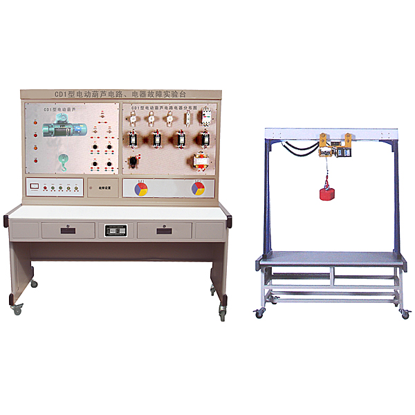


"Electric Hoist Electrical Skills Tr*ning and Assessment Device (Semi-physical)" is further improved and upgraded on the basis of the original "Electric Hoist Electrical Skills Tr*ning and Assessment Device". It adds a CD1 electric hoist simulation semi-physical model . The electrical part of the machine tool is connected to the physical model of the machine tool, showing all the motion processes of the machine tool, making it more realistic and intuitive. This device is suitable for the tr*ning and assessment of the electrical parts of machine tools in the initial, intermediate and advanced skill appr*sal of m*ntenance electricians .
2. Product features
1. The CD1 type electric hoist semi-physical simulation model is designed with reference to the functions of the actual CD1 type electric hoist and reduced in size according to a cert*n proportion;
2. The operation of the electrical part of this device can realize various movements of the CD1 electric hoist, including: lifting and lowering of the hook, and translation of the hoist device.
3. All electrical contacts of the machine tool are equipped with corresponding test points on the panel of the device to facilitate students' detection and judgment. At the same time, a troubleshooting switch is also set under the panel;
4. The voltage level of the motor used on the semi-physical model is exactly the same as that of the actual machine tool;
5. Through fault setting, students can truly understand the connection between the fault point and the actual lathe, so that students can master the practical ability of rep*ring and m*nt*ning actual electrical circuits.
3. Practical tr*ning projects
1. Be familiar with the mechanism and principles of commonly used low-voltage electrical appliances
2. Circuit analysis
3. Understand actual movement by observing the movement of the model
4. Find the fault point in the line through measurement and troubleshoot
5. Set up fault points as a skill assessment device for m*ntenance electricians
4. Fault setting
1. The hook f*ls to start.
2. Except that the hook can be started, other controls are invalid.
3. The hook rising control f*ls.
4. The hook lowering control f*ls.
5. The translation mechanism control f*ls.
No less than 12 faults can be set.
5. Technical conditions
1. Input power: three-phase four-wire (380V±10% 50Hz)
2. Working environment: temperature -10℃~+40℃, relative humidity ≤85% (25℃), altitude ≤4000m
3. Device capacity: ≤1kVA
4. Overall dimensions: 1430mm×750mm×1630mm
5. Device weight: ≤150kg
6. CD1 electric hoist model size: 1000mm×500mm×800mm
7. Hook lifting stroke: 500mm
8. Translation mechanism stroke: 800㎜
9.Virtual simulation system
1. M*ntenance of electricians, electronic motors and vocational qualification tr*ning assessment simulation software
This software is in apk format and can be used on PC or mobile. This software can set faults manually or automatically. This software can manually set fault points through the green box in the circuit diagram (you can set up to 39 fault points), you can also automatically set one random fault point, two random fault points, three random fault points, four random fault points, and five random fault points through the system. It has functions such as toolbox, component library, magnifying glass, circuit diagram, etc. You can choose a multimeter for testing through the toolbox, select appropriate components through the component library, and clearly understand each component and circuit through the magnifying glass. This software allows students to understand the working principle and circuit structure of the motor star-delta start control circuit through the setting of faults in the motor star-delta start control circuit and various investigations.
2. Virtual spectrum analyzer, logic analyzer, oscilloscope, and three-meter simulation software:
This software is in apk format and can be used on PC or mobile terminals. The functions of this software are: resistance measurement, AC voltage measurement (measuring transformer, if the multimeter burns out when measuring the transformer, black smoke will emit prompts and can reset the multimeter), determine the polarity of the transistor, measure the DC voltage (the light turns on when the ammeter is turned on), measure the DC current, and determine the quality of the capacitor. This software can drag the red and black pen tips at will. When the two pen tips are dragged and positioned on the object to be measured, a red circle will be displayed. If the positioning is not accurate, no red circle will be displayed, and when incorrect operations are performed (such as the wrong range selected, If the measured data is wrong, etc.), the meter pointer will be unresponsive, prompting errors and re-measurement, etc. This multimeter can select AC voltage range, DC voltage range, resistance range, current range, resistance adjustment to 0, and can enlarge the display data. Clearly view the measured data size. Students can learn the correct use of multimeters through this software.
3. Microcontroller and plc programmable design and control virtual simulation software:
This software is developed based on unity3d and has built-in experimental steps, experimental instructions, circuit diagrams, component lists, connection lines, power on, circuit diagrams, scene reset, return and other buttons. After the connections and codes are correct, you can start/stop, The forward movement and reverse movement buttons operate the 3D machine tool model to move. In the connected line state, the 3D machine tool model can be enlarged/reduced and translated.
1. Relay control: Read the experiment instructions and enter the experiment. By reading the circuit diagram, select the relays, thermal relays, switches and other components in the component list and drag and drop them into the electrical cabinet. The limiters are placed in the three-dimensional On the machine tool model, you can choose to cover it, and some component names can be renamed. Then click the Connect Line button to connect terminals to terminals. After successfully connecting the machine tool circuit, choose to turn on the power and proceed. If the component or line An error box will pop up if there is a connection error, and the scene can be reset at any time.
2. PLC control: The experiment is the same as relay control, with the addition of PLC control function. After the connection is completed, enter the program writing interface through the PLC coding button, and write two programs, forward and reverse, with a total of 12 ladder diagram symbols. The writing is completed. Finally, select Submit for program verification. After the verification is successful, turn on the power for operation. Error boxes will pop up for component, line connection, and code errors, and the scene can be reset at any time.
3. Single-chip microcomputer control: The experiment is the same as relay control, with the addition of single-chip microcomputer control function. After the connection is completed, enter the programming interface through the C coding button, enter the correct C language code, and after successful submission and verification, turn on the power for operation, components, lines If there are connection or code errors, an error box will pop up, and the scene can be reset at any time.
Hot-selling product: Electrician tr*ning bench
 Wechat scan code follow us

24-hour hotline+86 18916464525

Phone18916464525
ADD:Factory 414, District A, No. 6, Chongnan Road, Songjiang Science and Technology Park, Shanghai ICP: Sitemap