Shanghai Daiyu Education Equipment Manufacturing Co., Ltd.
Language:


Based on the design of the "Pilot Work Plan for the Teaching Reform of Work-Study Integrated Courses in Technical Colleges" of the Ministry of Human Resources and Social Security, the course objectives are determined around typical work tasks (i.e. FMS), the course content is selected, and professional teaching plans are formulated. According to the relevant national occupational standards The content combines electromechanical engineering with relevant majors such as "Electrical Technology", "Basic Electrical Skills", "Electrical Measurement and Instrumentation", " Motor and Electrical Control", "Motor Control Circuit", "Electric Drag Control Circuit" The modules are organically combined through the tr*ning of work tasks to quantify typical work tasks into multiple sub-tasks, and gradually implement the new concept of task-led, project-driven, modular teaching, follow the teaching rules, and use multimedia teaching and online teaching. and advanced means of situational teaching to simplify complex knowledge points and clarify profound theoretical points, close to the actual corporate work content and processes, and integrate the tr*ning workshop and the company, the tr*ning teachers and company employees, and the tr*ning content and The work tasks are truly integrated into one, achieving the purpose of integrated teaching with work and study.
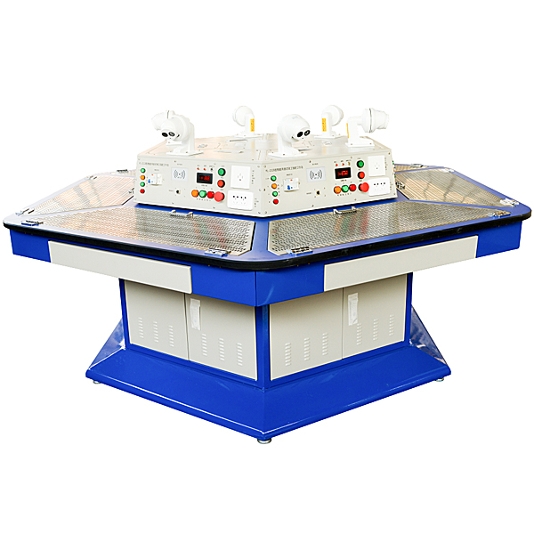
This area of the Electrician Skills Practical Tr*ning and Assessment Platform is centered on the Electrician Skills Work Island equipment and is built using industrial scenario-based facilities. It is equipped with a teaching-oriented work process and management system to allow students to conduct practical tr*ning and teaching through tasks. The equipment can be operated by 6 students at the same time, and they can carry out work tasks as a team and follow their own work processes through role division. In addition to practical tr*ning, theoretical teaching can be carried out to achieve the integration of "doing", "learning" and "teaching".
2. M*n technical parameters
1. Input power supply: three-phase five-wire AC380V±5% 50Hz;
2. Power output: 6 independent stations,
1) Fixed AC output for each workstation: three-phase five-wire 380V plug-in type 1 group, 220V socket type 2 groups
2) Adjustable DC output: 0~24V/2A continuously adjustable 2 groups (with pointer voltage and pointer ammeter to monitor power supply changes in real time);
3. Interfaces and instruments: 2 pointer voltmeters to monitor grid voltage changes at all times;
4. Protection: The fuse has short circuit protection, the circuit breaker has overload protection, the leakage switch has leakage protection function, and the leakage protection action current is ≤30mA.
5. Safety protection: Leakage protection (action current ≤30mA), overcurrent protection, fuse protection;
6. Rated power: ≤2KW;
7. Working environment: temperature -10℃~+40℃, relative humidity <85% (25℃), altitude <4000m
8. Overall dimensions: 2500*2115*780 (mm)
3. System composition
The skill work island consists of a hexagonal workbench, a hexagonal power control screen and typical work tasks, and can accommodate 6 students to operate on the equipment at the same time.
Hexagonal workbench: The table body is made of high-quality cold-rolled steel plates and is machined into shape. The whole machine is both sturdy and durable, and beautiful. The surface of the workbench is spray-coated with solid colors. The workbench is designed with six workstations. Each workstation is equipped with a double-door storage cabinet. The workstations are connected by arc-shaped transition plates. The desktop has a hexagonal structure and is made of 30mm thick solid core physical and chemical board, not high-density fireproof board. The outer surface is covered with fireproof board, and the table edge is rounded, making it beautiful and safe. The diameter of the workbench is 2500mm, and the height is designed according to ergonomic requirements, with a height of 750mm.
Hexagonal power control panel: The power control panel adopts a hexagonal structure, corresponding to the workbench, and has leakage protection and short-circuit protection functions. A multi-angle high-definition camera is installed on the top of the workbench to record each student's practical operation process.
The workbench is embedded with a practical mesh plate. When the mesh plate is closed, it is parallel to the work surface. When needed, it can be expanded to multiple angles for use.
virtual simulation system
1. M*ntenance of electricians, electronic motors and vocational qualification tr*ning assessment simulation software
This software is in apk format and can be used on PC or mobile. This software can set faults manually or automatically. This software can manually set fault points through the green box in the circuit diagram (you can set up to 39 fault points), you can also automatically set one random fault point, two random fault points, three random fault points, four random fault points, and five random fault points through the system. It has functions such as toolbox, component library, magnifying glass, circuit diagram, etc. You can choose a multimeter for testing through the toolbox, select appropriate components through the component library, and clearly understand each component and circuit through the magnifying glass. This software allows students to understand the working principle and circuit structure of the motor star-delta start control circuit through the setting of faults in the motor star-delta start control circuit and various investigations.
2. Virtual spectrum analyzer, logic analyzer, oscilloscope, and three-meter simulation software:
This software is in apk format and can be used on PC or mobile terminals. The functions of this software are: resistance measurement, AC voltage measurement (measuring transformer, if the multimeter burns out when measuring the transformer, black smoke will emit prompts and can reset the multimeter), determine the polarity of the transistor, measure the DC voltage (the light turns on when the ammeter is turned on), measure the DC current, and determine the quality of the capacitor. This software can drag the red and black pen tips at will. When the two pen tips are dragged and positioned on the object to be measured, a red circle will be displayed. If the positioning is not accurate, no red circle will be displayed, and when incorrect operations are performed (such as the wrong range selected, If the measured data is wrong, etc.), the meter pointer will be unresponsive, prompting errors and re-measurement, etc. This multimeter can select AC voltage range, DC voltage range, resistance range, current range, resistance adjustment to 0, and can enlarge the display data. Clearly view the measured data size. Students can learn the correct use of multimeters through this software.
3. Microcontroller and plc programmable design and control virtual simulation software:
This software is developed based on unity3d and has built-in experimental steps, experimental instructions, circuit diagrams, component lists, connection lines, power on, circuit diagrams, scene reset, return and other buttons. After the connections and codes are correct, you can start/stop, The forward movement and reverse movement buttons operate the 3D machine tool model to move. In the connected line state, the 3D machine tool model can be enlarged/reduced and translated.
1. Relay control: Read the experiment instructions and enter the experiment. By reading the circuit diagram, select the relays, thermal relays, switches and other components in the component list and drag and drop them into the electrical cabinet. The limiters are placed in the three-dimensional On the machine tool model, you can choose to cover it, and some component names can be renamed. Then click the Connect Line button to connect terminals to terminals. After successfully connecting the machine tool circuit, choose to turn on the power and proceed. If the component or line An error box will pop up if there is a connection error, and the scene can be reset at any time.
2. PLC control: The experiment is the same as relay control, with the addition of PLC control function. After the connection is completed, enter the program writing interface through the PLC coding button, and write two programs, forward and reverse, with a total of 12 ladder diagram symbols. The writing is completed. Finally, select Submit for program verification. After the verification is successful, turn on the power for operation. Error boxes will pop up for component, line connection, and code errors, and the scene can be reset at any time.
3. Single-chip microcomputer control: The experiment is the same as relay control, with the addition of single-chip microcomputer control function. After the connection is completed, enter the programming interface through the C coding button, enter the correct C language code, and after successful submission and verification, turn on the power for operation, components, lines If there are connection or code errors, an error box will pop up, and the scene can be reset at any time.
4. Possible work tr*ning tasks
1. Commonly used low-voltage electrical appliances in the first unit and their installation, testing and m*ntenance
1) Topic 1 Classification and common terms of low-voltage electrical appliances
2) Topic 2 low voltage fuse
3) Topic 3 low voltage switch
4) Topic 4 M*n Electrical Appliances
5) Subject 5 Contactor
6) Topic 6 Relay
2. The basic control circuit of the second unit motor and its installation, debugging and m*ntenance
1) Topic 1 Manual forward control circuit of three-phase cage asynchronous motor
2) Topic 2 Inching forward control circuit of three-phase cage asynchronous motor
3) Topic 3 Self-locking forward control circuit of three-phase cage asynchronous motor
4) Topic 4 Continuous and inching mixed forward control circuit of three-phase cage asynchronous motor
5) Topic 5 Forward and reverse control circuit of three-phase cage asynchronous motor
6) Topic 6 Position control and automatic reciprocating control circuit of three-phase cage asynchronous motor
7) Topic 7 Sequential control circuit of three-phase cage asynchronous motor
8) Topic 8 Multi-ground control circuit of three-phase cage asynchronous motor
9) Topic 9 Y-△ step-down starting control circuit of three-phase cage asynchronous motor
10) Topic 10 Reverse braking control circuit of three-phase cage asynchronous motor
11) Topic 11 Control circuit of two-speed asynchronous motor
12) Topic 12 Control circuit of three-phase wound rotor asynchronous motor
13) Topic 13 Motor Control, Protection and Selection
14) Topic 14 Basics of Electrical Control Circuit Design
3. The third unit frequency conversion speed regulation system
1) Topic 1 Basic knowledge of general-purpose inverters
2) Topic 2 Working principle and control function of inverter
3) Topic 3 Selection and installation of general-purpose inverter
4) Debugging of Topic 4 Frequency Conversion Speed System
5) Topic 5 M*ntenance and rep*r of universal frequency conversion speed control system
4. Unit 4 Programmable Control Technology
1) Topic 1 PLC controls the start and stop of a three-phase asynchronous motor
2) Topic 2 PLC controls the sequential start and stop of a three-phase asynchronous motor
3) Topic 3 PLC control of three-phase asynchronous motor inching and self-locking control
4) Topic 4 PLC controlled three-phase asynchronous motor Y-Δ starting control
5) Topic 5 PLC control of forward and reverse rotation of three-phase asynchronous motor
6) Topic 6 PLC controlled three-phase asynchronous motor with limit automatic reciprocating control
5. Unit 5 touch screen control technology
1) Topic 1 Touch screen programming
2) Topic 2 Touch screen and PLC communication
3) Topic 2 Control of touch screen, PLC, and inverter
5. Electrical Skills Island Tr*ning Equipment Configuration (Single Set Configuration)
|
serial number |
Name |
Models and specifications |
quantity |
|
1. |
Electrician skills tr*ning and assessment platform |
1 set |
|
|
2. |
st*nless steel mesh plate |
6 yuan |
|
|
3. |
software |
6 sets |
|
|
4. |
Practical tr*ning guide |
1 copy |
|
|
5. |
Leakage switch |
6A |
6 |
|
6. |
fuse |
5A |
12 pieces |
|
7. |
fuse |
3A |
24 |
|
8. |
AC contactor |
220V CJX2-0910 |
30 pieces |
|
9. |
Auxiliary contacts |
30 pieces |
|
|
10. |
thermal relay |
0.63-1A |
24 |
|
11. |
Thermal relay base |
24 |
|
|
12. |
Power on delay time relay |
0-30s |
12 pieces |
|
13. |
Power off delay time relay |
0-30s |
12 pieces |
|
14. |
Terminal block |
12 verses |
24 |
|
15. |
Terminal r*l |
200mm |
18 |
|
16. |
Button switch box (three switches) |
12 pieces |
|
|
17. |
Button switch box (two switches) |
12 pieces |
|
|
18. |
Button (without light) |
green red |
30 pieces |
|
19. |
Limit switch |
Automatic reset |
12 pieces |
|
20. |
Limit switch |
Manual reset |
12 pieces |
|
twenty one. |
Traction electromagnet |
220V |
6 |
|
twenty two. |
Reverse switch bracket |
KO3-15 |
6 |
|
twenty three. |
Plastic mounting clip |
800 pieces |
|
|
twenty four. |
St*nless steel self-tapping screws |
600 pieces |
|
|
25. |
indicator light |
220V |
18 |
|
26. |
guide |
3 meters |
|
|
27. |
Universal transfer switch bracket |
6 |
|
|
28. |
R*l mounting screws |
60 sets |
|
|
29. |
Mitsubishi programmable controller |
FX3U-32MR/ES-A |
6 |
|
30. |
Mitsubishi inverter |
FR-E740-0.75K-CHT |
6 |
|
31. |
Embedded integrated touch screen |
TPC7062Ti |
6 |
|
32. |
touch screen stand |
6 |
|
|
33. |
Three-phase asynchronous motor (380V, single speed) |
PN (W): 60, nN (r/min): 1400, UN (V): three-phase AC 380 IN (A): 0.33, connection group: △/Y |
6 units |
|
34. |
Three-phase asynchronous motor (380V, single speed with centrifugal switch) |
PN (W): 60, nN (r/min): 1400, UN (V): three-phase AC 380 IN (A): 0.33, connection group: △/Y |
6 units |
|
35. |
Three-phase two-speed asynchronous motor |
PN(W):40/25, nN(r/min):2800/1400, UN(V): Three-phase AC 380 IN(A):0.25/0.2, Connection group: △/2Y |
6 units |
|
36. |
Mitsubishi download line |
6 items |
|
|
37. |
Touch screen download line |
6 items |
|
|
38. |
communication line |
PLC and touch screen communication |
6 items |
|
39. |
Needle nose pliers |
6 inches |
6 |
|
40. |
Wire strippers |
6 |
|
|
41. |
wire cutters |
6 inches |
6 |
|
42. |
Slotted screwdriver |
3 inches |
6 |
|
43. |
Phillips screwdriver |
3 inches |
6 |
|
44. |
test pencil |
DL8001 |
6 |
|
45. |
multimeter |
MY60 |
6 |
|
46. |
Electrician's knife |
Deli DL0060 |
6 |
|
47. |
Diagonal pliers |
6 inches |
6 |
|
48. |
Crimping Tool |
HS-06WF (pressing pin) |
6 |
|
49. |
Steel tape |
3m |
6 |
|
50. |
Slotted screwdriver |
2×75 |
6 |
|
51. |
Phillips screwdriver |
2×75 |
6 |
Wire list
|
serial number |
Name |
Models and specifications |
quantity |
|
1 |
Soft cord |
0.75mm two-color |
6 volumes |
|
2 |
Soft cord |
0.75mm green |
6 volumes |
|
3 |
Soft cord |
0.75mm blue |
6 volumes |
|
4 |
Soft cord |
0.75mm yellow |
6 volumes |
|
5 |
Soft cord |
0.75mm red |
6 volumes |
|
6 |
Pin |
E1008 |
1000 pieces |
|
7 |
electrical tape |
6 |
|
|
8 |
Row trunking |
3025 |
6 meters |
|
9 |
hardwired |
1mm two-color |
6 volumes |
|
10 |
hardwired |
1mm green |
6 volumes |
|
11 |
hardwired |
1mm blue |
6 volumes |
|
12 |
hardwired |
1mm yellow |
6 volumes |
|
13 |
hardwired |
1mm red |
6 volumes |
|
14 |
Ties |
3×100mm |
100 pieces |
|
15 |
Special number tube |
1.5mm2 |
1 package |
Overall standard configuration/1 set (users can bring their own)
|
serial number |
Name |
Specifications/Models |
unit |
quantity |
Remark |
|
1 |
terminal video recorder |
tower |
1 |
||
|
2 |
camera |
Only |
6 |
||
|
3 |
harddisk |
Only |
1 |
||
|
4 |
Positioning bracket |
Only |
6 |
||
|
5 |
Install wires |
set |
1 |
||
|
6 |
split screener |
2 in 1 out |
Only |
1 |
 Wechat scan code follow us

24-hour hotline+86 18916464525

Phone18916464525
ADD:Factory 414, District A, No. 6, Chongnan Road, Songjiang Science and Technology Park, Shanghai ICP: Sitemap