Shanghai Daiyu Education Equipment Manufacturing Co., Ltd.
Language:


PLC programmable controller is a new industrial control device developed based on microcomputer. With its small size, strong functions, high reliability and easy application and installation, it quickly occupied a dominant position in my country's industrial control and continues to develop. According to this development situation, all major technical secondary schools and various vocational and technical schools in the country have included PLC teaching in their teaching tasks as a required course for electronics , electrical and industrial automation majors. The PLC programming experimental system is a new generation of PLC teaching product developed based on this teaching requirement. Since the launch of the product, it has received unanimous pr*se from teaching teachers and experts in major colleges and universities. The complete set of devices has reasonable design, powerful functions, and simple and convenient operation. It is of great help to students in understanding and mastering the control principles and replacement methods of programmable controllers and accelerating learning of PLC programming methods. It is an ideal tool for PLC teaching.
2. Functional features
1. Power module: 220V AC power supplies power to the device after passing through the *r switch. The grid voltmeter monitors the grid voltage and is equipped with fuse protection. The power supply of the control panel is controlled by a leakage protection switch and a start-stop switch; a set of single-phase 220V power supply is provided by The start-stop switch controls the output and is protected by a fuse.
2. DC voltage: 24V, +5V output, 0~±10V adjustable output; DC current: 4~50mA adjustable output;
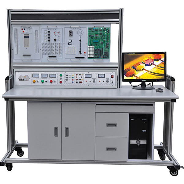
3. Tr*ning table: The tr*ning table has an aluminum-wood structure, and the desktop is made of fireproof, waterproof, and wear-resistant high-density board; the cabinet is equipped with drawers for placing tools and information, and the computer desk is designed as a joint.
3. Technical parameters
1. Input power supply: m*ns ~220V±10%, power frequency 50Hz;
2. Ambient temperature: -5℃~+40℃, relative humidity <85% (25℃);
3. Device capacity: <1.5KVA;
4. Overall dimensions: 1600mm×730mm×1700mm
5. Safety protection: It has leakage voltage and leakage current protection devices, and is safe and in line with national standards. Use high-insulation safety sockets and high-strength safety experimental wires with insulating sheaths.
4. Configuration list:
1. Tr*ning table
2. Tr*ning platform
3. PLC host module: Mitsubishi FX2N-48MR (input 24 points, output 24 points).
4. Module hanging box:
PLC tr*ning module one:
1) Music fount*n simulation control 2) Clicker simulation control 3) Assembly line simulation control 4) Crossroad traffic light simulation control 5) Automatic rolling mill simulation control 6) Sky Tower Light/TV Tower radio wave simulation control
PLC tr*ning module two:
1) Automatic feeding and loading/conveyor belt simulation control 2) Multiple liquid mixing device/mixer simulation control 3) Vending machine simulation control 4) Water tower automatic water supply simulation control 5) M*l sorting simulation control
PLC tr*ning module three:
1) Basic input/output experiment 2) Four-story elevator automatic control 3) Intermediate relay
PLC tr*ning module four:
1) Electroplating system simulation control 2) Washing machine automatic control 3) LED seven-segment digital tube display control
5. Safety plug-in and pull-out cables, 10 pcs: 1000mm long; 40 pcs: 600mm long;
6. Equipped with PLC programming software, PLC learning software, programming cables and related operation manuals (paper).
7. Microcontroller and PLC programmable design and control virtual simulation software:
This software is developed based on unity3d and has built-in experimental steps, experimental instructions, circuit diagrams, component lists, connection lines, power on, circuit diagrams, scene reset, return and other buttons. After the connections and codes are correct, you can start/stop, The forward movement and reverse movement buttons operate the 3D machine tool model to move. In the connected line state, the 3D machine tool model can be enlarged/reduced and translated.
1. Relay control: Read the experiment instructions and enter the experiment. By reading the circuit diagram, select the relays, thermal relays, switches and other components in the component list and drag and drop them into the electrical cabinet. The limiters are placed in the three-dimensional On the machine tool model, you can choose to cover it, and some component names can be renamed. Then click the Connect Line button to connect terminals to terminals. After successfully connecting the machine tool circuit, choose to turn on the power and proceed. If the component or line An error box will pop up if there is a connection error, and the scene can be reset at any time.
2. PLC control: The experiment is the same as relay control, with the addition of PLC control function. After the connection is completed, enter the program writing interface through the PLC coding button, and write two programs, forward and reverse, with a total of 12 ladder diagram symbols. The writing is completed. Finally, select Submit for program verification. After the verification is successful, turn on the power for operation. Error boxes will pop up for component, line connection, and code errors, and the scene can be reset at any time.
3. Single-chip microcomputer control: The experiment is the same as relay control, with the addition of single-chip microcomputer control function. After the connection is completed, enter the programming interface through the C coding button, enter the correct C language code, and after successful submission and verification, turn on the power for operation, components, lines If there are connection or code errors, an error box will pop up, and the scene can be reset at any time.
8. Virtual spectrum analyzer, logic analyzer, oscilloscope, and three-meter simulation software:
This software is in apk format and can be used on PC or mobile terminals. The functions of this software are: resistance measurement, AC voltage measurement (measuring transformer, if the multimeter burns out when measuring the transformer, black smoke will emit prompts and can reset the multimeter), determine the polarity of the transistor, measure the DC voltage (the light turns on when the ammeter is turned on), measure the DC current, and determine the quality of the capacitor. This software can drag the red and black pen tips at will. When the two pen tips are dragged and positioned on the object to be measured, a red circle will be displayed. If the positioning is not accurate, no red circle will be displayed, and when incorrect operations are performed (such as the wrong range selected, If the measured data is wrong, etc.), the meter pointer will be unresponsive, prompting errors and re-measurement, etc. This multimeter can select AC voltage range, DC voltage range, resistance range, current range, resistance adjustment to 0, and can enlarge the display data. Clearly view the measured data size. Students can learn the correct use of multimeters through this software.
9. Microcontroller tr*ning module
1. Monochrome running water lamp module: 8 high-brightness green patch 0805 package LED lights
2. Two-color running water light module: 6 high-brightness in-line LED lights, three colors: red, yellow and green
3. Two-color LED light module: red and green two-color direct plug-in LED light
4.8-bit digital tube module: 2 four-bit common anode digital tubes, 2 74HC595 driver chips.
5.1-digit digital tube module: 1 8-segment digital tube, common anode, 0.56 inches
6. Red and green two-color dot matrix module: 3 74HC595 driver chips, one red and green two-color dot matrix display.
7.LCD1602 LCD screen module: standard LCD1602 LCD screen interface, 1 LCD1602 LCD screen with backlight.
8.8 independent buttons: 8 independent SMD buttons with pull-up resistors
9.4X4 matrix keyboard: 4 rows and 4 columns matrix keyboard, a total of 16 SMD buttons, with pull-up resistors.
10. Five-way joystick: A five-way joystick with five directions: up, down, left, right, and center.
11. Buzzer module: passive buzzer
12.DS1302 clock module: DS1302 chip, SOP8 package, module with battery holder on the back.
13. Two-way DS18B20 module: Two-way DS18B20 temperature sensor interface
14. Photosensitive sensor module: Integrated LM393 comparator, reference voltage adjustable resistor, analog output interface, digital output interface, analog indicator LED light, supports photoelectric switching devices such as photodiodes and photoresistors.
15. Flame sensor module: integrated LM393 comparator, reference voltage adjustable resistor, analog output interface, digital output interface, analog indicator LED light, supports flame sensor.
16. Hall sensor module: integrated LM393 comparator, reference voltage adjustable resistor, analog output interface, digital output interface, analog indicator LED light, supports Hall sensor.
17. Electrical control module
18. DC motor interface: ULN2003 driver chip, SMD SOP16 package. One-way speed-adjustable DC motor interface; One-way speed-adjustable and adjustable-direction dual-function motor interface
19. 2-way stepper motor interface: 2 ULN2003 driver chips, SOP16 package. Two standard 5-wire 4-phase stepper motor interfaces
20.2-way relay: ULN2003 driver chip, SOP16 package. Two 5V relays, two 3P terminal blocks.
21.2-channel serial port: SP3232 chip, SOP16 package, +3.0v-+5V working voltage, one male serial port socket, one female serial port socket, and 4 status indicators.
22.AT24C02 memory module: AT24C02 chip, SOP8 package
23. Analog input module: 0V-5V input is adjustable, 0R-10K resistance value is adjustable.
24. Serial to parallel module: 74HC164 chip, SOP14 package
25. Parallel to serial module: 74HC165 chip, SOP16 package
26.SD card module: standard SD card slot, SPI control, 4-bit transmission mode
27.MAX485 module: MAX485 chip, 1 set of 2P terminal outputs and 1 set of pin outputs.
28. Infrared emission module: infrared emission diode
29. Infrared receiving module: HX838 infrared integrated receiving head
30. PCF8591 AD/DA module: PCF8591 chip, SOP16W package, 4 analog inputs, 1 analog output, IIC communication.
31. Latch module: 74HC573 latch chip, compatible with standard CMOS
32. 38 decoder: 74LS138 chip, TTL level
33. Core board expansion interface: interface socket 29P two rows, IO expansion pin 28P two rows
5. Experimental content
1. Experiment on AND, OR and non-logical functions
2. Timer and counter function experiments
3. Jump and branch function experiments
4. Shift register experiment
5. Data processing function experiment
6. Differential and bit operation experiments
7. Music fount*n simulation control experiment
8. Clicker simulation control experiment
9. Simulation control experiment of assembly line
10. Crossroad traffic light simulation control experiment
11. Automatic rolling mill simulation control experiment
12. Sky Tower Light/TV Tower Radio Wave Simulation Control Experiment
13. Automatic feeding and loading/conveyor belt simulation control experiment
14. Simulation control experiment of various liquid mixing devices/mixers
15. Vending machine simulation control experiment
16. Water tower automatic water supply simulation control experiment
17. M*l sorting simulation control experiment
18. Four-story elevator automatic control experiment
19. Intermediate relay experiment
20. Electroplating system simulation control experiment
21. Washing machine automatic control experiment
22. LED seven-segment digital tube display control experiment
 Wechat scan code follow us

24-hour hotline+86 18916464525

Phone18916464525
ADD:Factory 414, District A, No. 6, Chongnan Road, Songjiang Science and Technology Park, Shanghai ICP: Sitemap