Shanghai Daiyu Education Equipment Manufacturing Co., Ltd.
Language:


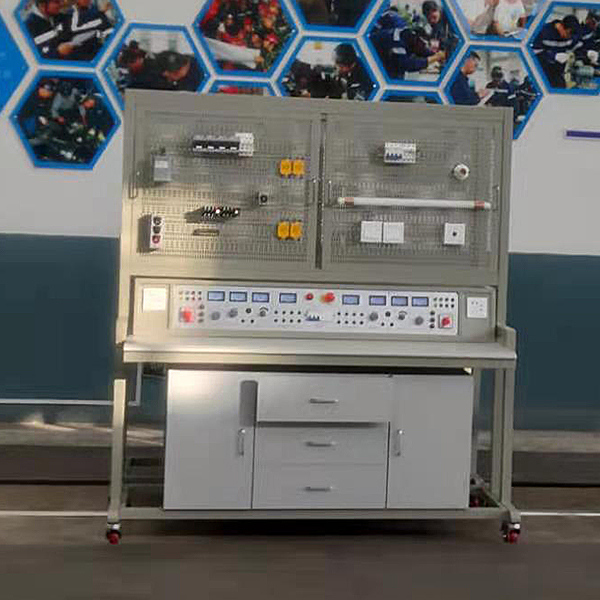


This equipment consists of a multi-functional mounting plate (mesh plate) tr*ning platform made of steel plates and a power supply device. Various components, devices and parts selected during practical tr*ning can be easily installed on the mesh board, which is convenient and flexible.
According to the needs of teaching and practical tr*ning, different components, devices and components can be selected to carry out different course modules and practical tr*ning for different projects. This equipment has a wide range of applications and can complete many teaching contents and practical tr*ning projects. Used components, devices and parts are removed from the tr*ning platform and stored centrally to avoid damage and loss. One tr*ning place can complete teaching and tr*ning in several majors and is economical and applicable.
The tr*ning platform is equipped with leakage protection, overload and circuit protection to ensure personal safety and safe use of equipment.
Flexible, reliable, safe, economical and applicable are the characteristics of this equipment. For schools with limited tr*ning venues and limited teaching funding, this equipment is an ideal vocational education tr*ning equipment.
2. Equipment technical indicators
1. Appearance: overall size 1632mm×750mm×1638mm;
2. Materials of the tr*ning bench: steel plate, aluminum alloy structure;
3. Power supply: 1) Input: three-phase AC 380V ±10% 50HZ three-phase five-wire; 2) Fixed AC output: three-phase five-wire 380V plug-in type 2 groups, 220V plug-in type 2 groups, 220V socket type 4 groups 3) Adjustable DC output: 0~24V/2A continuously adjustable 2 groups (with pointer voltage and pointer ammeter to monitor power supply changes in real time);
4. Interfaces and instruments: 2 pointer voltmeters to monitor grid voltage changes at all times;
5. Protection: The fuse has short circuit protection, the circuit breaker has overload protection, the leakage switch has leakage protection function, and the leakage protection action current is ≤30mA.
3. Equipment structure and function
This tr*ning platform consists of three parts: a tr*ning screen (built-in power supply), a tr*ning table, and a tr*ning locker. 30mm×30mm formed square steel is used as the m*n frame material of the equipment; the tr*ning screen and floor are welded and connected, and key parts are reinforced with triangular ribs and hexagonal socket screws. The surface is treated with high-temperature spray plastic, which is beautiful and elegant and effectively acts as an anti-rust insulation. The function of the mesh plate fixing mechanism is composed of two 35mm×35mm aluminum alloy profiles and chutes. Below the fixing mechanism is an iron double-station power box. The layout of each station power box is a power protection device and a power indicator. device, power output; the top of the tr*ning table is made of 25mm heather gray high-density laminate edge sealing, which effectively improves the insulation level; the bottom of the experimental table is equipped with at least 4 guide wheels to facilitate the movement of the tr*ning bench;
The tr*ning locker adopts a standard structure and drawer type. There are three drawers on the left side for storing tools and tr*ning materials. The double sliding door design on the right side can store two universal hanging boards at the same time. The position of the tr*ning locker can be flexibly adjusted according to needs, and the overall dimensions are: 1300mm×600mm×510mm.
virtual simulation system
1. M*ntenance of electricians , electronic motors and vocational qualification tr*ning assessment simulation software
This software is in apk format and can be used on PC or mobile. This software can set faults manually or automatically. This software can manually set fault points through the green box in the circuit diagram (you can set up to 39 fault points), you can also automatically set one random fault point, two random fault points, three random fault points, four random fault points, and five random fault points through the system. It has functions such as toolbox, component library, magnifying glass, circuit diagram, etc. You can choose a multimeter for testing through the toolbox, select appropriate components through the component library, and clearly understand each component and circuit through the magnifying glass. This software allows students to understand the working principle and circuit structure of the motor star-delta start control circuit through the setting of faults in the motor star-delta start control circuit and various investigations.
2. Virtual spectrum analyzer, logic analyzer, oscilloscope, and three-meter simulation software:
This software is in apk format and can be used on PC or mobile terminals. The functions of this software are: resistance measurement, AC voltage measurement (measuring transformer, if the multimeter burns out when measuring the transformer, black smoke will emit prompts and can reset the multimeter), determine the polarity of the transistor, measure the DC voltage (the light turns on when the ammeter is turned on), measure the DC current, and determine the quality of the capacitor. This software can drag the red and black pen tips at will. When the two pen tips are dragged and positioned on the object to be measured, a red circle will be displayed. If the positioning is not accurate, no red circle will be displayed, and when incorrect operations are performed (such as the wrong range selected, If the measured data is wrong, etc.), the meter pointer will be unresponsive, prompting errors and re-measurement, etc. This multimeter can select AC voltage range, DC voltage range, resistance range, current range, resistance adjustment to 0, and can enlarge the display data. Clearly view the measured data size. Students can learn the correct use of multimeters through this software.
3. Microcontroller and plc programmable design and control virtual simulation software:
This software is developed based on unity3d and has built-in experimental steps, experimental instructions, circuit diagrams, component lists, connection lines, power on, circuit diagrams, scene reset, return and other buttons. After the connections and codes are correct, you can start/stop, The forward movement and reverse movement buttons operate the 3D machine tool model to move. In the connected line state, the 3D machine tool model can be enlarged/reduced and translated.
1. Relay control: Read the experiment instructions and enter the experiment. By reading the circuit diagram, select the relays, thermal relays, switches and other components in the component list and drag and drop them into the electrical cabinet. The limiters are placed in the three-dimensional On the machine tool model, you can choose to cover it, and some component names can be renamed. Then click the Connect Line button to connect terminals to terminals. After successfully connecting the machine tool circuit, choose to turn on the power and proceed. If the component or line An error box will pop up if there is a connection error, and the scene can be reset at any time.
2. PLC control: The experiment is the same as relay control, with the addition of PLC control function. After the connection is completed, enter the program writing interface through the PLC coding button, and write two programs, forward and reverse, with a total of 12 ladder diagram symbols. The writing is completed. Finally, select Submit for program verification. After the verification is successful, turn on the power for operation. Error boxes will pop up for component, line connection, and code errors, and the scene can be reset at any time.
3. Single-chip microcomputer control: The experiment is the same as relay control, with the addition of single-chip microcomputer control function. After the connection is completed, enter the programming interface through the C coding button, enter the correct C language code, and after successful submission and verification, turn on the power for operation, components, lines If there are connection or code errors, an error box will pop up, and the scene can be reset at any time.
4. Examples of typical tr*ning projects that can be completed by this equipment
1. Practical tr*ning on lighting circuit installation and connection;
2. Fluorescent lamp connection tr*ning;
3. Application of single-phase electric energy meter;
4. Practical tr*ning on the connection of motor inching and continuous rotation circuits;
5. Practical tr*ning on connection of forward and reverse circuits of button interlocking motors;
6. Practical tr*ning on connecting the forward and reverse circuits of motors with contactor interlocking;
7. Practical tr*ning on connecting the forward and reverse circuits of the motor with double interlocking of contactors and buttons;
8. Installation of motor control circuits controlled in two places;
9. Practical tr*ning on connection of motor stator winding series resistor starting control circuit;
10. Connection tr*ning of Y-△ start control circuit for button switching;
11. Connection tr*ning of Y-△ start control circuit for time relay switching;
12. Motor half-wave rectification energy consumption brake control circuit connection tr*ning;
13. Motor full-wave rectification energy consumption braking control circuit connection tr*ning;
14. Motor reverse braking control circuit connection tr*ning;
15. Practical tr*ning on electric motor round trip control circuit connection;
16. Motor sequence starting control circuit connection tr*ning;
17. Motor timing operation control circuit connection tr*ning;
18. Practical tr*ning on connection of two-speed motor control circuit with button switching;
19. Two-speed motor control circuit connection tr*ning for time relay switching;
Hot-selling product: Electrician tr*ning bench
 Wechat scan code follow us

24-hour hotline+86 18916464525

Phone18916464525
ADD:Factory 414, District A, No. 6, Chongnan Road, Songjiang Science and Technology Park, Shanghai ICP: Sitemap