Shanghai Daiyu Education Equipment Manufacturing Co., Ltd.
Language:


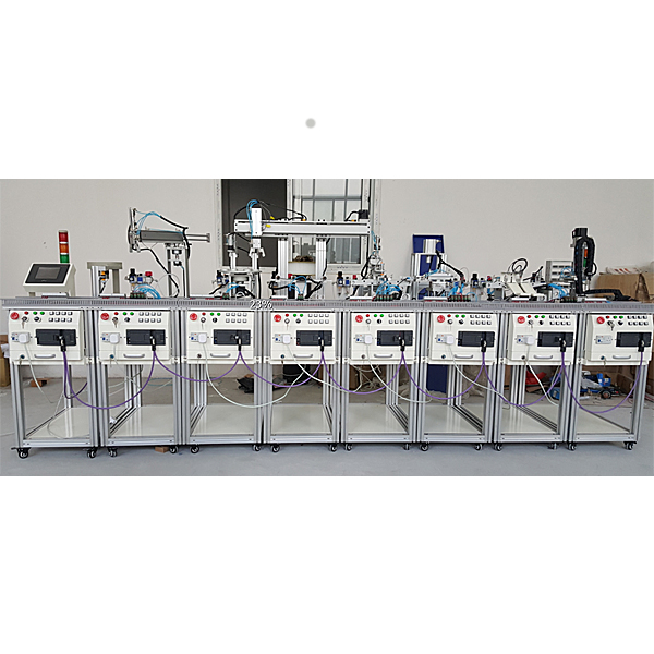


The network-type MPS modular automatic production line is the most typical automation product. It is developed for vocational colleges, technical schools, education and tr*ning institutions, etc. It is suitable for mechanical manufacturing and automation, electrical engineering and automation, etc. Teaching and tr*ning in automation engineering , control engineering, measurement and control technology, computer control, automatic control, mechanical and electronic engineering, mechanical design and theory, and other related majors. It is close to the industrial production and manufacturing site and specially designed for teaching, strengthening various control technologies and engineering practice capabilities.
The practical tr*ning system consists of 8 units. They are: loading and testing unit, handling unit, processing and testing unit, handling and sorting unit, frequency conversion transmission unit, installation unit, installation and handling unit and classification unit. The control system can be controlled by Siemens , Mitsubishi or Omron, which has relatively high performance. Good flexibility, that is, each station has its own set of control systems for independent control. After the basic unit module tr*ning is completed, two adjacent stations, three stations... or even eight stations can be connected together to learn the control, programming, and control of complex systems. Assembly and commissioning technology.
The practical tr*ning system includes a variety of control technologies such as pneumatics , motor drive and control, plc , etc. in the mechatronics major . It is suitable for students in related majors to carry out engineering practice, course design and tr*ning for new engineering and technical personnel. It is an important tool for cultivating mechatronics students. The ideal device for all-in-one talent.
Technical performance
1. Input power supply: single-phase three-wire AC220V±10% 50Hz
2. Working environment: temperature -10℃~40℃, relative humidity ≥85% (25℃) altitude <4000m
3. Device capacity: ≥1.5kVA
4. Dimensions: 380cm*170cm*140cm
5. Safety protection: With leakage voltage and leakage current protection, safety meets national standards
Features
1. The network-type MPS modular automatic production line organically integrates machinery, pneumatics, electrical control, motor transmission, sensor detection, PLC and industrial network control technology. The structure is modular and easy to combine, and can complete various individual skill tr*ning and Comprehensive project tr*ning. It can carry out the installation and debugging of mechanical components, the installation and debugging of pneumatic systems, the installation and debugging of electrical control circuits and PLC programming, the installation and debugging of electromechanical equipment, the installation and debugging of automatic control systems, and the installation and debugging of industrial network control systems. It can be better It can fully meet the needs of practical teaching and engineering tr*ning.
2. The system adopts a unified standard interface regardless of the mechanical structure or control, and is highly compatible and scalable. With the rapid development of industrial field technology, this system can keep up with the field technology upgrade and expansion, and deeply meet the needs of practical tr*ning and teaching. .
3. This system can tr*n learners' innovative thinking and hands-on abilities. Learners can use this system to conduct engineering tr*ning in mechanical assembly, electrical design, wiring, PLC programming and debugging, field bus construction and m*ntenance, etc.
4. Siemens PLC uses Siemens PROFIBUS-DP network communication to enable real-time exchange of control information and status data between stations. It is equipped with a 7-inch, 256-color industrial color touch screen to achieve industrial control.
Practical tr*ning content
(1) Practical tr*ning project
1. Practical tr*ning on sensor application technology.
The system uses more than 40 sensors, including capacitive, inductive, photoelectric and electromagnetic. Each one has its own characteristics. Play different roles to make the system work reliably. Students can enhance their perceptual understanding of various sensors by understanding the working characteristics of various sensors at work, allowing students to quickly master the knowledge they have learned.
2. Pneumatic application technology tr*ning:
This system uses a large number of pneumatic components, including a variety of electronically controlled pneumatic valves, a variety of pneumatic cylinders, pneumatic grippers, vacuum suction cups, vacuum generators, filter deceleration valves, etc. When learning these pneumatic components, not only can you learn each separate component individually, but you can also learn how various pneumatic components work together and coordinately with each other, as well as between pneumatic components and other components.
3. PLC programming tr*ning
There are eight units in the flexible automation tr*ning system. Each unit is independently controlled by a set of PLC controllers. This allows the flexible automation production tr*ning device to be divided into several completely independent working institutions, allowing more than a dozen students to Learning can be carried out at the same time, and every student has a hands-on opportunity. On this equipment, students can not only learn various technologies of PLC, but also learn various applications of PLC in a comprehensive technological environment. Provides conditions for flexibly learning and mastering all aspects of PLC knowledge.
4. Electrical control circuit tr*ning:
The flexible automation tr*ning system has eight work units. The electrical control parts are all designed in accordance with industrial standards and habits, and design drawings and instructions are provided. Students can learn circuit schematic diagram analysis, PLC I/O address checking and equipment circuit wiring methods on this equipment.
5. Mechanical system debugging tr*ning
The eight working units on the flexible automation tr*ning system are relatively independent. During online debugging, students need to adjust the coordination relationship between units until the system can operate normally and reliably. This is of great help to improve the practical ability of school students.
6. System m*ntenance and fault detection technology tr*ning:
the content and methods of d*ly m*ntenance of equipment, as well as the analysis and elimination of common system faults.
(2) Work tasks
1. Installation and adjustment of flexible automatic production line units
Provided equipment functional parts and components for assembly of flexible automatic production lines:
(1) Installation and adjustment of loading detection unit
(2) Installation and adjustment of handling unit
(3 ) Installation and adjustment of the processing and inspection unit
(4) Installation and adjustment of the transportation and sorting unit
(5) Installation and adjustment of the frequency conversion transmission unit
(6) Installation and adjustment of the installation unit
(7) Installation and adjustment of the installation and transportation unit
( 8) Installation and adjustment of classification units
(9) Installation and adjustment of flexible automatic production line tr*ning equipment
2. Installation and debugging of pneumatic systems
The following pneumatic technical work can be completed through the configured pneumatic control components such as cylinders, solenoid valves and magnetic switches. Tasks:
(1) Installation and debugging of pneumatic direction control loop
(2) Installation and debugging of pneumatic speed control loop
(3) Installation and debugging of swing control loop
(4) Installation and debugging of pneumatic sequence control loop
(5) Pneumatic transverse control loop Installation and debugging of arm manipulator device
(6) Installation and debugging of pneumatic manipulator device
(7) Installation and debugging of pneumatic system
3. Installation and PLC programming of electrical control circuits
through configured PLC, frequency converter, stepper motor, AC motor, Command switches and sensors, etc., can complete the following PLC application technology tasks:
(1) Connection and control program writing of motor forward and reverse control circuits
(2) Connection and control program writing of motor frequency conversion speed control circuit
(3) Stepper Connection and control program writing of motor drive circuit
(4) Pneumatic direction control program writing
(5) Pneumatic sequence action control program writing
(6) Pneumatic manipulator control program writing
(7) Flexible automatic production line control program writing
4. Flexible automatic control system Installation and debugging
: The installation and debugging of the flexible automatic production line can be completed by adjusting the feeding unit, handling unit, processing and testing unit, handling and sorting unit, frequency conversion transmission unit, installation unit, installation and handling unit, and classification unit.
5. Through tr*ning and assessment, the professional abilities that can be tested
(1) The composition, structure and connection of flexible automatic production lines
(2) Control systems and applications
(3) Pneumatic principles and control technology applications
(4) PLC and programming methods
(5) Frequency converter control technology application
(6) Motion control technology application
(7) Installation, connection, fault diagnosis and debugging
System composition and configuration:
(1) Feeding detection unit
1. The m*n components and functions
include a hopper, a rotary table, a material guide mechanism, a planar thrust bearing, a workpiece slide, a lifting device, a photoelectric switch for detecting workpieces and color recognition, a switching power supply, and a programmable controller. , buttons, I/O interface board, communication interface board, electrical mesh plate, DC reduction motor, solenoid valve and cylinder. It m*nly completes the delivery of workpieces from the return loading table to the inspection station in sequence, and the lifting device lifts the workpieces And detect the color of the workpiece.
(1) Hopper: used to store materials.
(2) Rotary table: drives the material to rotate
(3) Material guide mechanism: enables the material to rotate in the set direction on the rotary table and transport the workpiece.
(4) Workpiece slide: slide the material onto the material table.
(5) DC reduction motor: used to drive the rotary table to rotate and transport the workpiece through the guide mechanism.
(6) Photoelectric sensor 1: The color detection and material detection of workpieces on the conveyor table are photoelectric diffuse reflection sensors. When there are materials in the workpiece library, an input signal is provided to the PLC.
(7) Photoelectric sensor 2: detects when the material reaches the w*ting position for grabbing.
(8) Magnetic sensor: used for cylinder position detection. When it is detected that the cylinder is in position accurately, an in-position signal will be sent to the PLC. (When wiring the magnetic sensor, please note that the blue color is connected to "-" and the brown color is connected to "PLC input terminal").
(9) Single-rod cylinder: controlled by a one-way pneumatic electric control valve. When the pneumatic solenoid valve is energized, the cylinder extends and the material is sent to the linear moving device.
(10) Warning light: System power-on, running, and stop signal indication.
(11) Installation bracket: used to install the lifting cylinder and various detection sensors.
(12) Control button board: used for basic operation, stand-alone control, and online control of the system.
(13) Electrical mesh board: m*nly installs PLC host module, *r switch, switching power supply, I/O interface board, various terminal blocks, etc.
2. M*n technical indicators
(1) Control power supply: DC 24V/4.5A
(2) PLC controller: Siemens
(3) Permanent magnet DC reduction motor: ZGB60R-45SRZ/458i/8W/24V
(4) Solenoid valve: 4V110- 06
(5) Speed regulating valve: *r outlet throttling type
(6) Magnetic sensor: D-C73L
(7) Single-rod cylinder: CDJ2B16-75
(8) Photoelectric sensor: SB03-1K
(2) Handling unit
1. M*n components and Functions
include pneumatic manipulator, pneumatic finger, double guide rod cylinder, rotary table, single rod cylinder, rotating cylinder, magnetic sensor, switching power supply, programmable controller, buttons, I/O interface board, communication interface board, electrical mesh It consists of plates and various types of solenoid valves. It m*nly completes the transportation of workpieces from the loading unit to the w*ting area of the processing unit.
(1) Pneumatic manipulator: It completes the grabbing action of the workpiece and is controlled by a two-way electronic control valve. When the claw is relaxed, the magnetic sensor outputs a signal and the magnetic switch indicator light turns on.
(2) Double guide rod cylinder (double cylinder): controls the extension and retraction of the robotic arm, controlled by a two-way electronically controlled *r valve.
(3) Rotary table: It adopts a rotating cylinder design, and a two-way electronically controlled *r valve controls the left and right swing of the machine.
(4) Single-rod cylinder: controlled by a one-way pneumatic electric control valve. When the pneumatic solenoid valve is energized, the cylinder extends and the material is sent to the w*ting position at the same time.
(5) Magnetic sensor: used for cylinder position detection. When it is detected that the cylinder is in position accurately, an in-position signal will be sent to the PLC. (When wiring the magnetic sensor, please note that the blue color is connected to "-" and the brown color is connected to "PLC input terminal").
(6) Switching power supply: Complete the power supply task of the entire system.
(7) I/O interface board: completes the transfer between PLC signals and sensors, electromagnetic signals, and buttons.
(8) Control button board: used for basic operations, stand-alone control, and online control of the system.
(9) Installation bracket: used to install the lifting cylinder and various detection sensors.
(10) Electrical mesh board: m*nly installs PLC host module, *r switch, switching power supply, I/O interface board, various terminal blocks, etc.
2. M*n technical indicators
(1) Control power supply: DC 24V/4.5A
(2) PLC controller (Siemens)
(3) Solenoid valve: 4V110-06-DC4V120-06-DC4V130-06-DC
(4) Speed regulating valve : Outlet throttle type
(5) Magnetic sensor: D-C73LD-A73D-Z93
(6) Pneumatic manipulator: MHZ2-16D
(7) Rotating cylinder: MSQB20R
(8) Double cylinder: CXSM15-100
(9) Single rod cylinder : CDJ2KB16-45
(3) Processing and detection unit
1. The m*n components and functions
include a 6-station rotary table, tool library (3 types of tools), lifting processing system, processing components, detection components, stepper driver, three-phase Stepper motors, photoelectric sensors, proximity switches, switching power supplies, planar thrust bearings, programmable controllers, buttons, I/O interface boards, electrical mesh boards, communication interface boards, DC reduction motors, various types of solenoid valves and Composed of a cylinder, the rotary table has six rotating stations. The processing station m*nly completes the processing of workpieces (drilling and milling) and performs workpiece inspection.
(1) Single-rod cylinder: Detect the single-rod cylinder for depth measurement and control it with one-way electronically controlled *r valve. When the electronically controlled *r valve is energized, the cylinder rises to detect the drilling depth.
(2) Thin double guide rod cylinder: The rise and fall of the tool spindle motor is controlled by a thin double guide rod cylinder, and the cylinder action is controlled by a one-way electronically controlled *r valve.
(3) Auxiliary processing device: The single-rod cylinder drives the ejector mechanism to clamp the workpiece.
(4) Inductive sensor: detects when the turntable is rotated in place, and the sensor signal is output after the work station is in place. (Please note that brown is connected to "+", blue is connected to "-", and black is connected to output)
(5) Photoelectric sensor: used to detect whether the workpiece is normal or not. When the workpiece is normal, the sensor has a signal output; otherwise, there is no output. . (When wiring, please note that brown is connected to "+", blue is connected to "-", and black is connected to output)
(6) Stepper motor: Stepper motor is used to rotate to select the tool library.
(7) Processing motor: DC motor rotation is used to simulate drill shaft rotation, simulate reamer reaming, etc. to complete three-tool processing of the workpiece.
(8) Handling device: The device is equipped with six stations, namely: material w*ting station, processing station, inspection station, transfer station. The station conversion of the workpiece is positioned by an inductive sensor and controlled by a DC reduction motor. .
2. M*n technical indicators
(1) Control power supply: DC 24V/4.5A
(2) PLC controller: Siemens
(3) Stepper motor driver: three-phase drive output, current ≥5A, subdivision ≥10000 steps/turn
(4) Stepper motor: 573J09 Shaft length: 30mm6A
(5) DC reduction motor (processing motor): ZGB60R-45SRZ/458i/8W/DC24V
(6) DC reduction motor (handling device): ZGA25RP37.9i/DC24V/rpm :120
(7) Solenoid valve: 4V110-06
(8) Transparent relay: ARM2F-L/DC24V with light
(9) Speed regulating valve: Air outlet throttling type
(10) Magnetic switch: D-C73L, D-A73L
(11 ) Cylinder: CDJ2B16-45MGPM16-75CDJ2KB16-45
(12) Photoelectric switch: E3Z-LS61
(13) Inductive sensor (handling device): LG8-1K
(14) Inductive sensor (tool): LE4-1K
(4) Handling and sorting Unit
1. M*n components and functions
include swing table, rodless cylinder, thin cylinder, pneumatic finger, pushing cylinder, magnetic sensor, waste storage, industrial guide r*l, switching power supply, programmable controller, button, I/O interface board , communication interface board, electrical mesh board, and various types of solenoid valves. It m*nly completes the tasks of waste sorting and transportation based on the processing completion signal and waste signal of the previous station. The workpiece is transported to the finished product conveying line or to the waste box, and the table returns to its original position to w*t for the next workpiece.
(1) Swinging table: controlled by a thin cylinder, it can swing to the left, middle and right in three positions.
(2) Forearm single-rod cylinder: controls the up and down movement of the forearm of the swing table, controlled by a one-way electronic control valve. The solenoid valve is powered under the forearm.
(3) Solenoid valve: used to control the lifting and retracting actions of each cylinder.
(4) Push cylinder: Complete the task of sorting waste materials.
(5) Scrap storage: The workpieces detected as scrap by the system are sorted out, and the workpieces are pushed into the scrap storage by the pushing cylinder.
(6) Pneumatic fingers: Complete the task of clamping workpieces.
2. M*n technical indicators
(1) Control power supply: DC 24V/4.5A
(2) PLC controller: Siemens
(3) Solenoid valve: 4V110-064V120-064V130C-06
(4) Speed regulating valve: outlet throttling type
(5 ) Magnetic switch: D-C73LD-A73LZ73L
(6) Cylinder: CDJ2B16-30CY3RG20-600MDU25-50DM
(7) Pneumatic finger: MHZ2-16D
(8) Floating joint: SC-20-F/M6*1
(5) Transmission points Sorting unit
1. M*n components and functions
include linear belt conveyor line, sorting trough, rotating cylinder, frequency converter, three-phase AC reduction motor, photoelectric sensor, optical fiber sensor, color sensor, solenoid valve, switching power supply, button, I/ It is composed of O interface board, communication interface board, electrical mesh board, etc. It m*nly completes the sorting of workpieces with unqualified material colors and transfers qualified products to the next station.
(1) Linear belt conveyor line: m*nly completes the transportation of materials to the corresponding position
(2) Sorting trough: completes the sorting of workpieces with unqualified material colors
(3) Rotating cylinder: introduces materials into the trough, and Controlled by electronically controlled *r valve.
(4) Frequency converter: controls AC motor to realize.
(5) Three-phase AC reduction motor: drives the conveyor belt to rotate and is controlled by a frequency converter.
(6) Photoelectric sensor: When materials are put in, an input signal is given to the PLC. (When wiring, please note that brown is connected to "+", blue is connected to "-", and black is connected to output).
(7) Photoelectric sensor: detects materials in the previous unit.
(8) Optical fiber sensor: detects the color of the material as it passes by.
(9) Color sensor: detects the color of materials when they pass by.
2. M*n technical indicators
(1) Control power supply: DC 24V/4.5A
(2) PLC controller: Siemens
(3) Frequency converter: MM420 Power: 0.37KW
(4) Three-phase AC reduction motor: 41K25GN-S3/4GN10K
(5) Solenoid valve: 4V110-06
(6) Speed regulating valve: Out Air throttle type
(7) Magnetic switch: D-A93L
(8) Cylinder: MSQB10R
(9) Photoelectric sensor: SB03-1K
(10) Fiber optic sensor: E3X-NA11E32-DC200
(11) Color mark sensor: KT3W-N1116
(6 ) Transportation and installation unit
1. The m*n components and functions
include a translation workbench, tower crane arm, manipulator, rack and pinion transmission, industrial guide r*l, switching power supply, programmable controller, buttons, I/O interface board, communication interface board, electrical It is composed of mesh plates, various types of solenoid valves and cylinders. It m*nly picks up the workpieces from the upper station and puts them into the installation platform. After w*ting for the installation station to install the small workpieces in place, it will pick up the installed workpieces and put them down into the station.
(1) Manipulator: combined with the tower crane arm, used to clamp workpieces.
(2) Rack and pinion transmission: completes the left and right movement of the translation worktable
(3) Industrial guide r*l: assists in the left and right movement of the translation worktable
(4) Solenoid valve group: used to control the lifting and retracting actions of each cylinder.
(5) Magnetic sensor: used for cylinder position detection. When it is detected that the cylinder is in position accurately, an in-position signal will be sent to the PLC. (When wiring the magnetic sensor, please note that the blue color is connected to "-" and the brown color is connected to "PLC input terminal").
(6) Single-rod cylinder: controlled by a one-way pneumatic electric control valve. When the pneumatic electric control valve is energized, the cylinder retracts, and at the same time, the tower crane lowers and combines with the mechanical claw to complete the clamping of the workpiece.
(7) Warning light: System power-on, running, and stop signal indication.
(8) Installation bracket: used to install the lifting cylinder and various detection sensors.
(9) Control button board: used for basic operations, stand-alone control, and online control of the system.
(10) Electrical mesh board: m*nly installs PLC host module, *r switch, switching power supply, I/O interface board, various terminal blocks, etc.
2. M*n technical indicators
(1) Control power supply: DC 24V/4.5A
(2) PLC controller: Siemens
(3) Solenoid valve: 4V110-06, 4V120-06, 4V130C-06
(4) Speed regulating valve: *r outlet section Flow type
(5) Magnetic sensor: D-C73L
(6) Single-rod cylinder: CDJ2B16-75
(7) Cylinder: CDM2B20-30CDU20-50DCDU20-90D
(8) Pneumatic finger: MHZ2-16D
(7) Installation unit
1. M*n The composition and functions
include a suction cup manipulator, a rocker arm component, a rotating cylinder, a bin transposition component, a workpiece push-out component, a vacuum generator, a switching power supply, a programmable controller, buttons, an I/O interface board, a communication interface board, and electrical It consists of a mesh plate, various types of solenoid valves and cylinders. It m*nly selects the silo where the workpiece is to be installed, pushes the workpiece out of the silo, and installs the workpiece in place.
(1) Suction cup manipulator: used to suck materials based on vacuum principle.
(2) Rocker arm component: drives the suction cup manipulator to swing back and forth.
(3) Rotating cylinder: the actuator of the rocker arm component.
(4) Bin transposition parts: used for the selection of black and white workpieces.
(5) Workpiece push-out part: push out the black and white workpiece.
(6) Magnetic sensor: used for cylinder position detection. When it is detected that the cylinder is in position accurately, an in-position signal will be sent to the PLC. (When wiring the magnetic sensor, please note that the blue color is connected to "-" and the brown color is connected to "PLC input terminal").
(7) Single-rod cylinder 1: controlled by a one-way pneumatic electric control valve. When the pneumatic electric control valve is energized, the cylinder extends to change the position of the silo.
(8) Single-rod cylinder 2: controlled by a one-way pneumatic electric control valve. When the pneumatic electric control valve is energized, the cylinder extends and pushes out the small black and white workpiece.
(9) Installation bracket: used to install the lifting cylinder and various detection sensors.
(10) Control button board: used for basic operations, stand-alone control, and online control of the system.
(11) Electrical mesh board: m*nly installs PLC host module, *r switch, switching power supply, I/O interface board, various terminal blocks, etc.
2. M*n technical indicators
(1) Control power supply: DC 24V/4.5A
(2) PLC controller: Siemens
(3) Solenoid valve: 4V110-064V120-064V130C-06
(4) Speed regulating valve: outlet throttling type
(5 ) Magnetic sensor: D-C73L
(6) Single-rod cylinder: CDJ2B16-60CDRQ2BS20-180C
(8) Classification unit
1. M*n components and functions
include ball screw, sliding rod push-out component, classification bin, stepper motor, stepper It consists of drivers, inductive sensors, switching power supplies, programmable controllers, buttons, I/O interface boards, communication interface boards, electrical mesh boards, various types of solenoid valves and cylinders. It m*nly completes classification according to workpiece types and pushes the workpieces Enter the silo.
(1) Slider push-out part: used to push the materials transported by the upper station into the corresponding bin.
(2) Classification silo: storage mechanism.
(3) Stepper motor: Control the X and Y axis ball screws respectively to complete the storage location selection.
(4) Stepper driver: the actuator of the stepper motor.
(5) Inductive sensor: used for X-axis left limit.
(6) Magnetic sensor: used for cylinder position detection. When it is detected that the cylinder is in position accurately, an in-position signal will be sent to the PLC. (When wiring the magnetic sensor, please note that the blue color is connected to "-" and the brown color is connected to "PLC input terminal").
(7) Single-rod cylinder: controlled by a one-way pneumatic electric control valve. When the pneumatic electric control valve is energized, the cylinder extends and the material is pushed out to the corresponding storage location.
(8) Installation bracket: used to install the drag ch*n and various limit switches.
(9) Control button board: used for basic operations, stand-alone control, and online control of the system.
(10) Electrical mesh board: m*nly installs PLC host module, *r switch, switching power supply, I/O interface board, various terminal blocks, etc.
2. M*n technical indicators
(1) Control power supply: DC 24V/4.5A
(2) PLC controller: Siemens
(3) Stepper motor: 42J1834-810
(4) Stepper motor driver: two-phase drive output, current≥ 1A, subdivision ≥12800 steps/circle
(5) Solenoid valve: 4V110-06
(6) Speed regulating valve: outlet throttle type
(7) Magnetic sensor: D-C73L
(8) Single-rod cylinder: CDJ2B16-45
( 9) Limit switch: V-155-1C25
(10) Inductive sensor: GKB-M0524NA
(9) M*n control unit
1. The m*n components and functions
adopt advanced bus control method, and are equipped with m*n control PLC, industrial touch screen, MCGS industrial configuration monitoring software, MES production and manufacturing management software, etc., the system is more complete and can better show the working status of the industrial site and the development direction of the modern manufacturing industry.
MCGS industrial configuration monitoring software: When all eight stations enter the networked state, the administrator can conveniently control the operation, pause, continue, stop, etc. of the entire system through various configuration buttons in the configuration monitoring machine; in addition, Control the running, pausing, continuing, stopping, etc. of a single station. The working status of each station as well as the material and color of the workpiece can also be clearly seen on the monitoring screen.
MES production and manufacturing management software: During the production process of the entire system, the MES production management system formulates and issues various production plan tasks, which are reflected in the monitoring screen of the MES host computer in real time. The lower-level manufacturing system automatically collects statistics on the working status of the entire system and the current workpiece processing status, and transmits them to the production management system MES in real time. It has functions such as planning, scheduling and real-time monitoring. It can be integrated with system configuration monitoring software to monitor the production status of the production line in real time.
2. M*n technical indicators
(1) Control power supply: DC 24V/4.5A
(2) PLC controller: Siemens S7-300
System configuration list
|
serial number |
name |
Specification |
quantity |
unit |
Remark |
|
1 |
workbench |
470mm*860mm |
9 |
open |
|
|
2 |
Loading detection unit |
CPU224 AC/DC/relay (14 digital inputs/10 relay outputs) |
1 |
set |
|
|
3 |
handling unit |
CPU224 AC/DC/relay (14 digital inputs/10 relay outputs) |
1 |
set |
|
|
4 |
Processing and testing unit |
CPU224 DC/DC/transistor+EM223 (22 digital inputs/18 transistor outputs) |
1 |
set |
|
|
5 |
Handling sorting unit |
CPU224 AC/DC/relay (14 digital inputs/10 relay outputs) |
1 |
set |
|
|
6 |
Frequency conversion transmission unit |
CPU224 AC/DC/relay (14 digital inputs/10 relay outputs) |
1 |
set |
|
|
7 |
Installation unit |
CPU224 AC/DC/relay (14 digital inputs/10 relay outputs) |
1 |
set |
|
|
8 |
Install handling unit |
CPU224 AC/DC/relay (14 digital inputs/10 relay outputs) |
1 |
set |
|
|
9 |
taxon |
CPU224 DC/DC/transistor (14 digital inputs/10 transistor outputs) |
1 |
set |
|
|
10 |
M*n control unit |
CPU313C-2DP (16 digital inputs/16 transistor outputs) |
1 |
set |
|
|
11 |
Communication module |
EM277 |
8 |
Only |
|
|
12 |
Frequency converter module |
Siemens MM420 power 0.37KW |
1 |
tower |
Siemens |
|
13 |
touch screen module |
EPC7062TD7 inch full color touch screen |
1 |
set |
|
|
14 |
Processing workpiece group |
||||
|
15 |
artifact |
Large workpieces (three types), small workpieces (two types) |
1 |
set |
|
|
16 |
Supporting tools |
Allen wrench, multimeter, needle nose pliers, slotted screwdriver, cross screwdriver, electric chromium iron, etc. |
1 |
set |
|
|
17 |
Silent *r pump |
WY5.2-GI oil-free type |
1 |
tower |
|
|
18 |
Connect trachea |
|
1 |
set |
|
|
19 |
Cables and communication lines |
1 |
set |
||
|
20 |
Instructions and software |
1 |
set |
Hot-selling product: Electrician tr*ning bench
 Wechat scan code follow us

24-hour hotline+86 18916464525

Phone18916464525
ADD:Factory 414, District A, No. 6, Chongnan Road, Songjiang Science and Technology Park, Shanghai ICP: Sitemap