Shanghai Daiyu Education Equipment Manufacturing Co., Ltd.
Language:


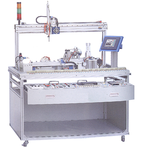


The recycling type optical electromechanical experimental bench consists of a profile guide r*l tr*ning bench , typical mechatronics equipment mechanical components, plc module, frequency converter module, button module, power supply module, and simulated production equipment tr*ning module (including loading unit, belt It consists of conveying detection unit, pneumatic manipulator handling unit, material transfer storage unit and return unit), touch screen, terminal block and various other components. Adopting an open and disassembly structure, production equipment can be assembled based on existing mechanical components, so that the entire device can flexibly assemble optical, mechanical and electrical integration equipment with production functions according to the requirements of practical tr*ning, teaching or competition. The modules adopt industrial standard structure and drawer-type module placement rack, which are highly interchangeable.
The tr*ning system integrates motion control, pneumatic control, stepper motor drive, servo motor drive, sensor detection, programmable control, and sequential logic control. Through the use, tr*ning and tr*ning based on this practical tr*ning system, the operator's teamwork ability, planning and organization ability, automatic line installation and debugging ability, project implementation ability, etc. can be fully developed. It is also suitable for students to carry out course design and graduation projects.
Technical indicators
(1) Input power supply: single-phase three-wire ~ 2200V±5% 50Hz
(2) Working environment: temperature -10℃ ~ +40℃, relative humidity ≥85% (25℃) altitude <4000m
(3) Device capacity: <1.5kVA
(4) Overall dimensions: 1200mm*800mm*1500mm
(5) Safety protection measures: It has grounding protection and leakage protection functions, and its safety complies with relevant national standards. Use high-insulation safety sockets and high-strength safety experimental wires with insulating sheaths.
Practical tr*ning project
Task 1: Installation and debugging of pneumatic system
(1) Installation of pneumatic direction control loop
(2) Installation of pneumatic speed control loop
(3) Installation of pneumatic sequence control loop
(4) Installation of pneumatic manipulator
(5) Pneumatic system *r circuit Connection
(6) Position adjustment of magnetic switch
(7) Pneumatic system debugging
Task 2: Installation and debugging of inverter, stepper motor and driver, servo motor and driver
(1) Connection of inverter and AC motor m*n circuit
(2 ) Parameter setting and operation of the inverter panel
(3) The inverter panel controls the speed of the AC motor
(4) Controls the start and stop of the motor through the external terminals of the inverter
(5) Selection of stepper motors and drivers
(6) Stepper motor Control loop connection
(7) Stepper motor debugging
(8) Servo motor and driver selection
(9) Servo motor control loop connection
(10) Servo motor debugging
Task 3: Installation and debugging of electromechanical equipment
(1) Part 1 Installation and debugging of material unit
(2) Installation and debugging of AC motor transmission device
(3) Installation and debugging of industrial encoder and adjustment of coaxiality
(4) Installation and debugging of material detection sensor
(5) Installation and debugging of pneumatic manipulator device
(6) Installation and debugging of stepper motor transmission device
(7) Installation and debugging of servo motor transmission device
(9) Installation and debugging of touch screen
(10) Installation and debugging of mechatronics equipment control loop
(11) Overall control loop of automatic production line Installation and debugging
Task 4: Installation of electrical control circuits and PLC programming
(1) Connection and programming of motor forward and reverse control circuits
(2) Connection and programming of motor speed control circuits
(3) Connection of motor closed-loop positioning control circuits and programming
(4) belt conveyor detection program writing
(5) pneumatic sequence action control program writing
(6) pneumatic manipulator control program writing
(7) stepper motor control circuit connection and control program writing
(8) servo motor control circuit connection and Control program writing
(9) Touch screen circuit connection and control screen writing
(10) Mechatronics equipment control program writing
(11) Automatic production line control program writing
Task 5: Installation and debugging of automatic control system
(1) Installation of various sensors and debugging
(2) Automatic control of belt conveyor detection
(3) Automatic control of manipulator
(4) Automatic control of material return unit
(5) Automatic control of electromechanical integration
(6) Installation and debugging of PLC control system
(7) Automatic Installation and debugging of the production line
Task 6: Design of the system to distinguish three different materials
(1) Installation and debugging of the automatic production line
(2) Programming to distinguish the three materials
Functional requirements
(1) Overall structure:
The recycling-type optical electromechanical experimental bench is assembled from a complete set of aluminum alloy tr*ning tables. Depending on the complexity of the tr*ning content, one or two tr*ning tables can be selected. The modules adopt standard structures and The drawer-type module placement rack has strong interchangeability; the module content is determined according to the principle of productive function and integrated learning function, so that the required modules can be easily selected during teaching or competition.
The I/O terminals of the PLC module, the wiring terminals of the frequency converter, and the connection terminals of common modules and PLC are all connected to safety sockets, and wires with safety plugs are used for circuit connections; each command switch, photoelectric switch, sensor and indicating element The circuit is connected through the terminal strip. The combination of plug-in and pull-out wire connection circuits and terminal block connection circuits not only ensures the tr*ning, formation and consolidation of students' basic skills, but also ensures the speed, safety and reliability of circuit connections.
(2) Requirements for each functional module:
1) Module material requirements: high-strength plastic shell, light weight, aluminum-plastic panel, and imported ink screen printing for patterns and text symbols. The human-machine interface adopts a color touch screen and comes with a mounting bracket that can be fixed to the aluminum alloy table of the tr*ning bench.
2) Power module: including 1 three-phase power m*n switch (with leakage and short-circuit protection), 3 fuses, 2 single-phase power sockets, 5 safety sockets; button module: 24 V/6 A; emergency stop 1 button, 2 transfer switches, 1 buzzer, 1 yellow, green and red reset button, 1 yellow, green and red self-locking button, 2 yellow, green and red 24V indicator lights.
3) Integrated terminal strip: There is a primary wiring area (terminal block) and a secondary wiring area (safety socket) on opposite sides of the terminal block housing; the terminal block and the corresponding safety socket are connected through conductive elastic parts; the terminal block housing The edge of the body is rolled up and equipped with screw holes for fixation, which can be fixed on the tr*ning table through screw rods.
4) Feeding device: composed of photoelectric sensor, single-rod gas, speed control valve, magnetic switch, single-control solenoid valve, material library, push block, material stopper, cylinder bracket, etc. Push the material blocks to the sorting device.
5) Material sorting device: The conveyor belt is driven by a three-phase asynchronous motor. A drop opening is designed at the end of the conveyor belt to detect materials through sensors. The conveyor belt uses a removable aluminum alloy bracket. The end has a rotary encoder.
6) Handling device: Three-degree-of-freedom pneumatic manipulator. The entire handling mechanism can complete three degrees of freedom movements, including arm rotation, claw up and down, and claw tightening. A sliding table with a guide rod is used for lifting, and a rotating cylinder with adjustable angle is used for rotation.
7) Transmission detection device: This transmission device adopts stepper motor drive, synchronous belt, synchronous wheel, and material pallet. Through the movement of the synchronous belt, the pallet is transported to the designated position for material sorting.
8) Return device: servo motor and driver, rack, gear, worm gear, two-axis cylinder, vacuum generator and vacuum suction cup. Responsible for quickly returning the sorted materials to the loading end.
9) Equipment bench: An aluminum alloy r*l-type tr*ning bench is used. The desktop profile is made of high-grade aluminum profiles with a cross-section of 20mm*80mm. It adopts a pull-out drawer structure. PLC, frequency converter and other modules can be placed on the drawer. The overall structure It is open and removable.
10) Virtual simulation system
1. M*ntenance of electricians , electronic motors and vocational qualification tr*ning assessment simulation software
This software is in apk format and can be used on PC or mobile. This software can set faults manually or automatically. This software can manually set fault points through the green box in the circuit diagram (you can set up to 39 fault points), you can also automatically set one random fault point, two random fault points, three random fault points, four random fault points, and five random fault points through the system. It has functions such as toolbox, component library, magnifying glass, circuit diagram, etc. You can choose a multimeter for testing through the toolbox, select appropriate components through the component library, and clearly understand each component and circuit through the magnifying glass. This software allows students to understand the working principle and circuit structure of the motor star-delta start control circuit through the setting of faults in the motor star-delta start control circuit and various investigations.
2. Virtual spectrum analyzer, logic analyzer, oscilloscope, and three-meter simulation software:
This software is in apk format and can be used on PC or mobile terminals. The functions of this software are: resistance measurement, AC voltage measurement (measuring transformer, if the multimeter burns out when measuring the transformer, black smoke will emit prompts and can reset the multimeter), determine the polarity of the transistor, measure the DC voltage (the light turns on when the ammeter is turned on), measure the DC current, and determine the quality of the capacitor. This software can drag the red and black pen tips at will. When the two pen tips are dragged and positioned on the measured object, a red circle will be displayed. If the positioning is not accurate, no red circle will be displayed, and when incorrect operations are performed (such as the wrong range selected, If the measured data is wrong, etc.), the meter pointer will not respond, prompting errors and re-measurement, etc. This multimeter can select AC voltage range, DC voltage range, resistance range, current range, resistance adjustment to 0, and can enlarge the display data. Clearly view the measured data size. Students can learn the correct use of multimeters through this software.
3. Microcontroller , PLC programmable design and control virtual simulation software:
This software is developed based on unity3d and has built-in experimental steps, experimental instructions, circuit diagrams, component lists, connection lines, power on, circuit diagrams, scene reset, return and other buttons. After the connections and codes are correct, you can start/stop, The forward movement and reverse movement buttons operate the 3D machine tool model to move. In the connected line state, the 3D machine tool model can be enlarged/reduced and translated.
1. Relay control: Read the experiment instructions and enter the experiment. By reading the circuit diagram, select the relays, thermal relays, switches and other components in the component list and drag and drop them into the electrical cabinet. The limiters are placed in the three-dimensional On the machine tool model, you can choose to cover it, and some component names can be renamed. Then click the Connect Line button to connect terminals to terminals. After successfully connecting the machine tool circuit, choose to turn on the power and proceed. If the component or line An error box will pop up if there is a connection error, and the scene can be reset at any time.
2. PLC control: The experiment is the same as relay control, with the addition of PLC control function. After the connection is completed, enter the program writing interface through the PLC coding button, and write two programs, forward and reverse, with a total of 12 ladder diagram symbols. The writing is completed. Finally, select Submit for program verification. After the verification is successful, turn on the power for operation. Error boxes will pop up for component, line connection, and code errors, and the scene can be reset at any time.
3. Single-chip microcomputer control: The experiment is the same as relay control, with the addition of single-chip microcomputer control function. After the connection is completed, enter the programming interface through the C coding button, enter the correct C language code, and after successful submission and verification, turn on the power for operation, components, lines If there are connection or code errors, an error box will pop up, and the scene can be reset at any time.
configuration list
|
serial number |
name |
M*n components or models and specifications |
quantity |
Remark |
|
1 |
Work tr*ning platform |
1200mm*800mm*800mm |
1 set |
|
|
2 |
Electrical control cabinet |
|
1 set |
|
|
3 |
PLC tr*ning module |
PLC host CPU226 (transistor output) |
1 item |
Siemens |
|
4 |
Frequency converter tr*ning module |
Frequency converter MM440, AC220V 0.75KW |
1 item |
Siemens |
|
5 |
Servo motor, controller |
|
1 set |
|
|
6 |
Power module |
1 m*n power switch (with leakage and short-circuit protection), 3 fuses, 2 power sockets |
1 item |
|
|
7 |
button module |
Switching power supply 24V/6A, 1 emergency stop button, 2 transfer switches, 1 buzzer, 1 yellow, green and red reset button, 1 yellow, green and red self-locking button, 24V indicator light yellow , green and red 1 each |
1 item |
|
|
8 |
Loading unit |
1 photoelectric sensor, 1 single-rod cylinder, 2 speed control valves, 2 magnetic switches, 1 single control solenoid valve, 1 material library, 1 nylon push block, 1 material stopper, 1 cylinder bracket |
1 item |
|
|
9 |
Belt conveyor detection unit |
1 three-phase AC reduction motor (AC380V, output speed 50r/min), 1 transmission belt 960*58*2mm, 1 capacitive sensor, 1 inductive sensor, 1 color sensor, 1 rotary encoder, 2 rollers Only, 1 set of belt mounting bracket |
1 item |
|
|
10 |
Pneumatic manipulator handling unit |
1 thin cylinder, 1 rotary cylinder, 1 pneumatic gripper, 5 magnetic switches, 3 single control solenoid valves, 6 speed control valves, 1 arm base |
1 item |
|
|
11 |
Material transfer storage unit |
1 synchronous belt, 2 synchronous wheels, 1 stepper motor, 1 driver, 1 flat shelf, 1 flat delivery table, 2 travel switches, 2 magnetic switches, 1 single control solenoid valve, push 1 cylinder, 2 debugging valves |
1 item |
|
|
12 |
Material return unit |
1 servo motor and driver, 1 synchronous belt, 1 synchronous wheel, 1 cylinder, 1 vacuum generator and 1 vacuum suction cup |
1 item |
|
|
13 |
touchscreen |
SMART700 IE with Ethernet |
1 item |
|
|
14 |
Terminal block |
Terminal blocks and safety sockets |
1 set |
|
|
15 |
materials |
2 each of metal (aluminum, iron), 2 each of red and yellow nylon |
6 |
|
|
16 |
Safety plug |
|
1 set |
|
|
17 |
trachea |
Some Ф4/Ф6 |
1 set |
|
|
18 |
PLC programming cable |
PC/PPI |
1 item |
|
|
19 |
PLC programming software |
|
1 set |
|
|
20 |
Supporting tools |
Tools: Medium and small Phillips screwdriver, clock screwdriver, wire strippers, needle nose pliers, scissors, soldering iron, tweezers, adjustable wrench, Allen wrench |
1 set |
|
|
twenty one |
Product supporting CD |
(User manual, supporting program, etc.) |
1 set |
|
|
twenty two |
Air compressor |
0.6~0.8MPa |
1 set |
 Wechat scan code follow us

24-hour hotline+86 18916464525

Phone18916464525
ADD:Factory 414, District A, No. 6, Chongnan Road, Songjiang Science and Technology Park, Shanghai ICP: Sitemap