Shanghai Daiyu Education Equipment Manufacturing Co., Ltd.
Language:


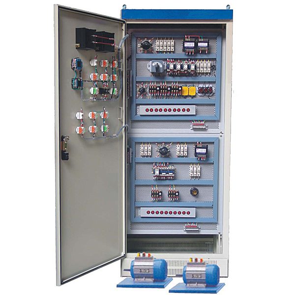


This machine tool electrical skills assessment and tr*ning device is used for the assessment of electrical majors and social electricians in various vocational colleges, as well as the teaching, practical tr*ning, internship, and assessment of units such as m*ntenance electricians in cities and counties , and the National Vocational and Technical Appr*sal Institute (station). A practical tr*ning assessment device developed for and skill appr*sal. Since the device all uses electrical appliances that are actually used in industry, it has good reliability and long life. The device has beautiful appearance, easy operation and strong intuitiveness. It can not only be used for classroom demonstrations, practical tr*ning and internships in related courses, but also can be used for tr*ning on machine tool electrical control circuit m*ntenance skills. In addition, it can also provide comprehensive and real machine tool electrical troubleshooting skill tr*ning, effectively improving students' m*ntenance skills of machine tool equipment.
2. Product features:
1. This device uses a standard power distribution cabinet as the m*n cabinet, making full use of the double-sided space of the cabinet. Each side is equipped with machine tool electrical circuits;
2. It is intuitive and can be familiar with the principles and characteristics of the electrical control circuit of the machine tool through operation;
3. The control circuits and specially designed motors used for skill tr*ning can simulate the electrical circuits of various actual machine tools, and can also meet the tr*ning requirements for the separation and elimination of electrical faults in machine tools;
4. Switching between two machine tool circuits can be achieved through a transfer switch, which is convenient and fast;
5. The fault point can be set manually by switching the switch;
6. The power distribution cabinet is equipped with a voltage type leakage protector and a current type leakage protector to ensure the safety of the operator. In addition, it is also equipped with a timer and alarm recorder, which provides a unified standard for the assessment of students.
3. Technical parameters
1. Input power: three-phase four-wire 380V±10% 50Hz
2. Working environment: Temperature: -10℃~+40℃ Relative humidity: ≤85% (25℃)
3. Device capacity: ≤1.5KVA
4. Product composition:
1. Tr*ning cabinet
The tr*ning cabinet is an iron matte dense spray-coated structure: it is extruded from cold-rolled steel plates. The tr*ning cabinet cont*ns four universal moving wheels with foot brakes. Overall dimensions: 700mm×600mm×1800mm. Equipment weight: 200kg, anti-electric shock protection level: Class I, safety protection: equipped with overcurrent, overload, leakage protection (leakage action current ≤30mA, breaking time ≤0.1S), in line with relevant national standards.
2. Cabinet door
(1) On the door of the control cabinet, there is an AC voltmeter, an AC ammeter, a timing and alarm recorder, a voltage indication switch, and start, stop, and emergency stop buttons.
The voltage indication switch can indicate the UUV, UVW, and UWU line voltage values of the power grid respectively; an AC ammeter is installed to monitor the load size.
The three-phase power input, after passing through the leakage protector, controls the contactor through the start and stop buttons to operate the output of the m*n power supply of the machine tool circuit. The emergency stop button is used as an emergency stop switch in the event of an accident.
The timer and alarm recorder is usually used as a clock and has functions such as setting tr*ning time, timing alarm, and cutting off power. In addition, it can also automatically record the number of leakage alarms caused by operating errors, providing a unified standard for the assessment of students' practical skills.
3. Mesh panels (two groups)
The mesh plate is made of high-quality cold-rolled steel plate, with a double-surface matte dense-gr*n spray-p*nted structure, making it sturdy and durable.
4. M*n body of control cabinet:
The control cabinet is divided into four parts
The first part is the electrical circuit part of the X62W universal milling machine. All the components of the X62W milling machine are installed on this panel.
The second part is the electrical circuit part of the CA6140 lathe. All components of the CA6140 lathe are installed on this panel.
The third part is the electrical circuit part of the T68 boring machine circuit. All components of the T68 boring machine circuit are installed on this panel.
The fourth part is the electrical circuit part of the Z3040 radial drilling machine. The 5. virtual simulation system of the Z3040 radial drilling machine is installed on this panel.
1. M*ntenance of electricians, electronic motors and vocational qualification tr*ning assessment simulation software
This software is in apk format and can be used on PC or mobile. This software can set faults manually or automatically. This software can manually set fault points through the green box in the circuit diagram (you can set up to 39 fault points), you can also automatically set one random fault point, two random fault points, three random fault points, four random fault points, and five random fault points through the system. It has functions such as toolbox, component library, magnifying glass, circuit diagram, etc. You can choose a multimeter for testing through the toolbox, select appropriate components through the component library, and clearly understand each component and circuit through the magnifying glass. This software allows students to understand the working principle and circuit structure of the motor star-delta start control circuit through the setting of faults in the motor star-delta start control circuit and various investigations.
2. Virtual spectrum analyzer, logic analyzer, oscilloscope, and three-meter simulation software:
This software is in apk format and can be used on PC or mobile terminals. The functions of this software are: resistance measurement, AC voltage measurement (measuring transformer, if the multimeter burns out when measuring the transformer, black smoke will emit prompts and can reset the multimeter), determine the polarity of the transistor, measure the DC voltage (the light turns on when the ammeter is turned on), measure the DC current, and determine the quality of the capacitor. This software can drag the red and black pen tips at will. When the two pen tips are dragged and positioned on the measured object, a red circle will be displayed. If the positioning is not accurate, no red circle will be displayed, and when incorrect operations are performed (such as the wrong range selected, If the measured data is wrong, etc.), the meter pointer will not respond, prompting errors and re-measurement, etc. This multimeter can select AC voltage range, DC voltage range, resistance range, current range, resistance adjustment to 0, and can enlarge the display data. Clearly view the measured data size. Students can learn the correct use of multimeters through this software.
3. Microcontroller and plc programmable design and control virtual simulation software:
This software is developed based on unity3d and has built-in experimental steps, experimental instructions, circuit diagrams, component lists, connection lines, power on, circuit diagrams, scene reset, return and other buttons. After the connections and codes are correct, you can start/stop, The forward movement and reverse movement buttons operate the 3D machine tool model to move. In the connected line state, the 3D machine tool model can be enlarged/reduced and translated.
1. Relay control: Read the experiment instructions and enter the experiment. By reading the circuit diagram, select the relays, thermal relays, switches and other components in the component list and drag and drop them into the electrical cabinet. The limiters are placed in the three-dimensional On the machine tool model, you can choose to cover it, and some component names can be renamed. Then click the Connect Line button to connect terminals to terminals. After successfully connecting the machine tool circuit, choose to turn on the power and proceed. If the component or line An error box will pop up if there is a connection error, and the scene can be reset at any time.
2. PLC control: The experiment is the same as relay control, with the addition of PLC control function. After the connection is completed, enter the program writing interface through the PLC coding button, and write two programs, forward and reverse, with a total of 12 ladder diagram symbols. The writing is completed. Finally, select Submit for program verification. After the verification is successful, turn on the power for operation. Error boxes will pop up for component, line connection, and code errors, and the scene can be reset at any time.
3. Single-chip microcomputer control: The experiment is the same as relay control, with the addition of single-chip microcomputer control function. After the connection is completed, enter the programming interface through the C coding button, enter the correct C language code, and after successful submission and verification, turn on the power for operation, components, lines If there are connection or code errors, an error box will pop up, and the scene can be reset at any time.
4. Experimental content
X62W milling machine circuit:
1. The spindle motor is missing one phase in both forward and reverse rotation, the feed motor and cooling pump are missing one phase, and the control transformer and lighting transformer are out of power;
2. The spindle motor starts out of phase;
3. The spindle motor is missing one phase regardless of forward or reverse rotation;
4. The spindle motor is missing one phase regardless of forward or reverse rotation;
5. The rapid feed electromagnet cannot move;
6. The lighting and control transformer is out of power, the lighting lamp does not light up, and the control circuit f*ls;
7. The control transformer is out of power and the control circuit f*ls;
8. Except for the cooling pump and spindle impulse, all other controls are invalid;
9. Spindle impulse f*lure;
10. Spindle brake f*lure;
11. Spindle startup f*lure;
12. Workbench feed control and rapid feed control f*l;
13. The spindle cannot be started;
14. The spindle point axis only moves inching and cannot self-lock;
15. The feed control and rapid feed of the circular worktable are completely disabled;
16. When the circular table control switch SA1 is in the off position, the feed control forward, downward, backward, and upward are invalid, and there is no feed impulse;
17. Feeding should not be impulsive;
18. Does the workbench move downward, right or forward?
19. When the circular workbench control switch SA1 is in the on position, all circular workbench controls will be disabled;
20. Both rapid feeds are disabled;
CA6140 lathe:
1. The spindle motor is out of phase and the circuit is broken before entering the KM1 contact;
2. The spindle motor is out of phase and has an open circuit between the KMM1 contact and FR1;
3. The control loop f*ls and the circuit is broken between FU1 and TC;
4. The tool holder rapid movement motor is missing one phase and is open between the FU1 and KA2 contacts;
5. The tool holder rapid movement motor is missing one phase, and the circuit is broken between the KA2 contact and the tool holder rapid movement motor;
6. The spindle motor, the tool holder moves quickly, the cooling pump control f*ls, and there is an open circuit between the transformer TC and FU2;
7. The spindle motor, tool holder rapid movement, and cooling pump controls f*led. There is an open circuit between the two normally closed contacts of the thermoelectric device FR1 and FR2;
8. The spindle motor cannot be started, and the circuit between KM1 wire package and TC is open;
9. The tool holder rapid movement and cooling pump control cannot be controlled. The connection between buttons SB1 and SB2 is disconnected;
10. The cooling pump control f*ls, and there is an open circuit between the start button QS2 and the KM1 normally open contact;
T68 boring machine circuit
1. All motors are missing phases and the control circuit f*ls;
2. The spindle motor and workbench motor are missing phases regardless of forward or reverse rotation, and the control loop is normal;
3. The spindle rotates forward and lacks phase;
4. Both forward and reverse rotation of the spindle are missing one phase;
5. One phase is missing when the feed motor moves forward rapidly;
6. The feed motor is missing one phase regardless of forward or reverse rotation;
7. The control circuit and lighting circuit are both out of power;
8. Except for the lighting and power-on indication, all other controls are disabled;
9. When SQ4 is pressed down on the operating handle, SQ3 is not pressed down (turned on), but the control circuit f*ls and the power-on indicator light is still on;
10. The spindle cannot be started when it rotates forward, but it can move inching;
11. The spindle motor’s forward rotation and start are invalid;
12. All control loops f*l;
13. The spindle motor cannot start or jog when it rotates reversely;
14. The spindle motor can only move in reverse direction;
15. The spindle motor cannot be reversed;
16. The high and low speed operation of the spindle motor and the rapid movement of the fast moving motor cannot be started;
17. When the spindle speed is changed or the feed speed is changed, SQ2 cannot be disconnected when the handle is pulled out, and M1 is still running;
18. The spindle motor does not start at both high and low speeds;
19. The spindle motor cannot be started at low speed, and there is no low-speed transition at high speed;
20. When the handle is moved to the feed position and SQ4 is pressed (SQ3 is turned on), the fast-moving motor will not start regardless of forward or reverse rotation;
21. The spindle motor can only run at low speed even if it reaches the high speed position;
22. The fast moving motor cannot start when it rotates forward;
24. The fast-moving motor cannot start regardless of forward or reverse rotation;
25. The motor moves quickly and cannot be started in reverse;
26. The motor moves quickly and cannot start in forward rotation;
Z3040 radial drilling machine
1. The transformer TC has no voltage input, so the control and indicator lights are invalid.
2. The column tightening motor loses power and cannot be loosened or clamped. All other controls are normal.
3. The cooling motor loses power and the cooling motor cannot operate.
4. Rocker arm lifting control f*lure
5. Cooling lighting is normal and other controls f*l.
6. The rocker arm can only rise, not fall.
7. The spindle can only go down, not up.
8. Spindle control f*lure
9. The column control can only be loosened, not clamped.
10. The column control can only be clamped and cannot be loosened.
 Wechat scan code follow us

24-hour hotline+86 18916464525

Phone18916464525
ADD:Factory 414, District A, No. 6, Chongnan Road, Songjiang Science and Technology Park, Shanghai ICP: Sitemap