Shanghai Daiyu Education Equipment Manufacturing Co., Ltd.
Language:


The machine tool electrical comprehensive tr*ning and assessment device is used for the assessment of electrical majors and social electricians in various vocational colleges , as well as the teaching, practical tr*ning, internship, assessment and skills of various municipal and county m*ntenance electricians , national vocational and technical appr*sal institutes (stations) and other units A practical tr*ning and assessment device developed for identification. Since the device all uses electrical appliances that are actually used in industry, it has good reliability and long life. The device has beautiful appearance, easy operation and strong intuitiveness. It can not only be used for classroom demonstrations, practical tr*ning and internships in related courses, but also can be used for tr*ning on machine tool electrical control circuit m*ntenance skills. In addition, it can also provide comprehensive and real machine tool electrical troubleshooting skill tr*ning, effectively improving students' m*ntenance skills of machine tool equipment.
2. Characteristics
1. This device uses a standard power distribution cabinet as the m*n cabinet, making full use of the double-sided space of the cabinet. The power distribution cabinet integrates two types of machine tool electrical circuits, so it has the characteristics of small footprint, beautiful appearance, and high economic benefits. .
2. It is intuitive and you can become familiar with the principles and characteristics of the electrical control circuit of the machine tool through operation.
3. The control circuits and specially designed motors used for skill tr*ning can simulate the electrical circuits of various actual machine tools, and can also meet the tr*ning requirements for electrical fault analysis and troubleshooting of machine tools.
4. Switching between two machine tool circuits can be achieved through a transfer switch, which is convenient and fast.
5. The fault point can be manually set by switching the switch.
6. The power distribution cabinet is equipped with a voltage type leakage protector and a current type leakage protector to ensure the safety of the operator. In addition, it is also equipped with a timer and alarm recorder (service manager), which provides a unified standard for the assessment of students.
3. Technical parameters of machine tool electrical skills tr*ning and assessment cabinet
1. Input voltage: three-phase four-wire ~ 380V ±10% 50Hz
2. Working environment: ambient temperature range is -5℃ ~ +40℃, relative humidity <85% (25℃)
3. Device capacity: <1.5KVA
4 , Dimensions: 800mm×600mm×1800mm
5. Equipment weight: 200kg
6. Cabinet material: 2MM cold-rolled steel for the m*n part, 1.2MMM cold-rolled steel for other parts.
4. The device m*nly consists of the following parts
1. The control
cabinet door is equipped with an AC voltmeter, an AC ammeter, a timing and alarm recorder, a voltage indication switch, and start, stop, and emergency stop buttons. The operation buttons and action instructions of the M7120 grinder and the C6140 ordinary lathe, as well as the switch switches of the two machine tool circuits;
through the voltage indication switch, the UUV, UVW, and UWU line voltage values of the power grid can be indicated on the voltmeter respectively; the AC ammeter is used to monitor The size of the load;
timer and alarm recorder (service manager), which is usually used as a clock and has functions such as setting tr*ning time, timing alarm, and cutting off power. In addition, it can also automatically record the number of leakage alarms caused by operating errors, providing a unified standard for the assessment of students' practical tr*ning skills.
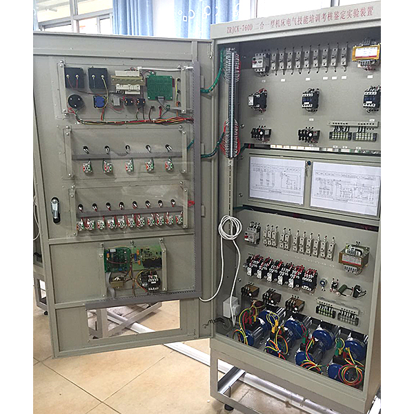
2. The m*n body of the control cabinet.
The control cabinet is divided into four parts.
The first part is the electrical circuit part of the M7120 grinder. All the components of the M7120 grinder are installed on this panel.
The second part is the fault setting box. There are two kinds of machine tools printed on the fault box cover. The electrical schematic diagram shows that there are 32 fault switches in the fault box, including 16 fault points for the M7120 grinder and 16 fault points for the C6140. The fault box door is equipped with a key for easy management and assessment;
the third part is for the C6140 ordinary The electrical circuit part of the lathe. All the components of the C6140 lathe are installed on this panel.
The fourth part is the motor panel. There are three motors. They are used to simulate the actions of various moving parts of the actual machine tool, and the wires of the motor and speed relay. All are led to the panel with pillars for easy testing.
3. Virtual simulation system
1. M*ntenance of electricians, electronic motors and vocational qualification tr*ning assessment simulation software
This software is in apk format and can be used on PC or mobile. This software can set faults manually or automatically. This software can manually set fault points through the green box in the circuit diagram (you can set up to 39 fault points), you can also automatically set one random fault point, two random fault points, three random fault points, four random fault points, and five random fault points through the system. It has functions such as toolbox, component library, magnifying glass, circuit diagram, etc. You can choose a multimeter for testing through the toolbox, select appropriate components through the component library, and clearly understand each component and circuit through the magnifying glass. This software allows students to understand the working principle and circuit structure of the motor star-delta start control circuit through the setting of faults in the motor star-delta start control circuit and various investigations.
2. Virtual spectrum analyzer, logic analyzer, oscilloscope, and three-meter simulation software:
This software is in apk format and can be used on PC or mobile terminals. The functions of this software are: resistance measurement, AC voltage measurement (measuring transformer, if the multimeter burns out when measuring the transformer, black smoke will emit prompts and can reset the multimeter), determine the polarity of the transistor, measure the DC voltage (the light turns on when the ammeter is turned on), measure the DC current, and determine the quality of the capacitor. This software can drag the red and black pen tips at will. When the two pen tips are dragged and positioned on the measured object, a red circle will be displayed. If the positioning is not accurate, no red circle will be displayed, and when incorrect operations are performed (such as the wrong range selected, If the measured data is wrong, etc.), the meter pointer will not respond, prompting errors and re-measurement, etc. This multimeter can select AC voltage range, DC voltage range, resistance range, current range, resistance adjustment to 0, and can enlarge the display data. Clearly view the measured data size. Students can learn the correct use of multimeters through this software.
3. Microcontroller and plc programmable design and control virtual simulation software:
This software is developed based on unity3d and has built-in experimental steps, experimental instructions, circuit diagrams, component lists, connection lines, power on, circuit diagrams, scene reset, return and other buttons. After the connections and codes are correct, you can start/stop, The forward movement and reverse movement buttons operate the 3D machine tool model to move. In the connected line state, the 3D machine tool model can be enlarged/reduced and translated.
1. Relay control: Read the experiment instructions and enter the experiment. By reading the circuit diagram, select the relays, thermal relays, switches and other components in the component list and drag and drop them into the electrical cabinet. The limiters are placed in the three-dimensional On the machine tool model, you can choose to cover it, and some component names can be renamed. Then click the Connect Line button to connect terminals to terminals. After successfully connecting the machine tool circuit, choose to turn on the power and proceed. If the component or line An error box will pop up if there is a connection error, and the scene can be reset at any time.
2. PLC control: The experiment is the same as relay control, with the addition of PLC control function. After the connection is completed, enter the program writing interface through the PLC coding button, and write two programs, forward and reverse, with a total of 12 ladder diagram symbols. The writing is completed. Finally, select Submit for program verification. After the verification is successful, turn on the power for operation. Error boxes will pop up for component, line connection, and code errors, and the scene can be reset at any time.
3. Single-chip microcomputer control: The experiment is the same as relay control, with the addition of single-chip microcomputer control function. After the connection is completed, enter the programming interface through the C coding button, enter the correct C language code, and after successful submission and verification, turn on the power for operation, components, lines If there are connection or code errors, an error box will pop up, and the scene can be reset at any time.
5. Completed practical tr*ning projects
1. Understand the structure of low-voltage electrical
2. C6140 ordinary lathe electrical control tr*ning
3. C6140 ordinary lathe electrical circuit troubleshooting assessment
4. M7120 grinder electrical control circuit tr*ning
5. M7120 grinder electrical control circuit troubleshooting assessment
6. By operating the machine tool, master Commonly used machine tool operating methods
Electrical control circuit distribution tables, two sets each on the front and back of the cabinet
|
equipment |
serial number |
Material name |
Specifications and models |
quantity |
Remark |
|
1. |
1 |
transfer switch |
LW5D-16/3,500V,16A |
1 |
|
|
2 |
fuse |
RT14-32 |
6 |
||
|
3 |
AC contactor |
LC1-D0910,110V |
3 |
||
|
4 |
transformer |
380V/110V, 24V, 6V |
1 |
||
|
5 |
thermal relay |
LR2-D1306 |
2 |
||
|
6 |
button |
XB4-Ø22 |
3 |
Φ22.5mm |
|
|
7 |
signal light |
6V/XB6-Ø16 |
1 |
Φ16mm |
|
|
8 |
flashlight |
24V/XB6-Ø16 |
1 |
Φ16mm |
|
|
9 |
Rotary Switches |
XB2-Ø22 |
2 |
Φ22.5mm |
|
|
2. |
1 |
transfer switch |
LW5D-16/3,500V,16A |
1 |
transfer switch |
|
2 |
fuse |
RT14-32 |
8 |
||
|
3 |
control transformer |
380V/110V |
1 |
||
|
4 |
lighting transformer |
380V/24V |
1 |
||
|
5 |
flashlight |
24V |
1 |
||
|
6 |
resistance |
680 Euro, 50W |
2 |
||
|
7 |
AC contactor |
CJ20-10,110V |
6 |
||
|
8 |
thermal relay |
JR36-20 |
3 |
||
|
9 |
AC electromagnet |
MQI-0.7N, 380V |
1 |
||
|
10 |
cross switch |
TCS30-1111-11/11/11/11 |
2 |
||
|
11 |
button |
LAY7 |
6 |
||
|
12 |
Rotary Switches |
LAY39 |
2 |
||
|
13 |
Combination Switch |
LW5D-16/3,500V,16A |
1 |
||
|
14 |
Combination Switch |
HZ1-10/E16, three pole, 10A |
1 |
||
|
15 |
Combination Switch |
HZ1-10/E16, two pole, 10A |
1 |
Optional machine tool circuit:
|
serial number |
Unit hanging board |
|
1 |
C650-2 ordinary lathe electrical control circuit |
|
2 |
M7120 surface grinder electrical control circuit |
|
3 |
M7130K surface grinder electrical control circuit |
|
4 |
M1432A universal cylindrical grinder electrical control circuit |
|
5 |
Z3050 radial drilling machine electrical control circuit |
|
6 |
Z35 radial drilling machine electrical control circuit |
|
7 |
CA6140 lathe circuit tr*ning assessment hanging board |
|
8 |
X62W milling machine circuit tr*ning assessment hanging board |
|
9 |
T68 boring machine circuit tr*ning and assessment hanging board |
|
10 |
Electric hoist circuit tr*ning and assessment hanging board |
|
11 |
Z3040B radial drilling machine electrical control circuit |
Hot-selling product: Electrician tr*ning bench
 Wechat scan code follow us

24-hour hotline+86 18916464525

Phone18916464525
ADD:Factory 414, District A, No. 6, Chongnan Road, Songjiang Science and Technology Park, Shanghai ICP: Sitemap