Shanghai Daiyu Education Equipment Manufacturing Co., Ltd.
Language:


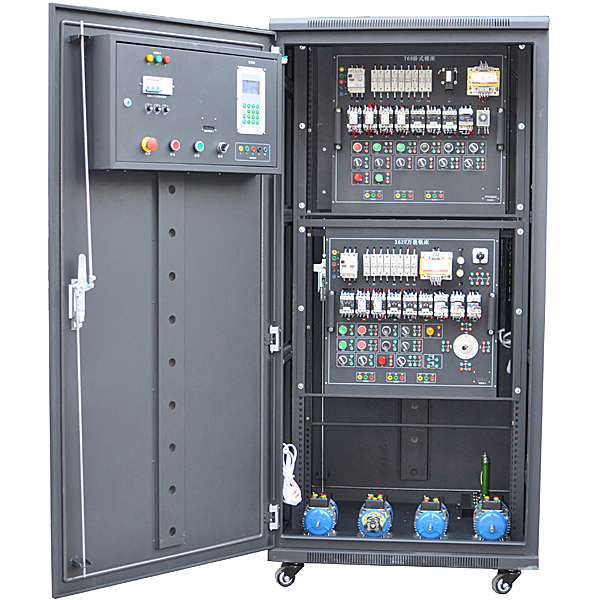


This device can complete " electrical technology", "factory electrical control", "machine tool line control", "programmable control
"Manufacturing Technology" and other practical tr*ning courses. The device resources are open and can fully cultivate students' practical ability, which is suitable for practical tr*ning in today's education and teaching. This device uses a standard power distribution cabinet as the m*n cabinet and a double-sided structure. Cont*ns the following resources: power control, three-phase AC power supply, DC power supply, excitation power supply, armature power supply, measuring instruments, programmable controller (Mitsubishi series), analog module, encoder, color touch screen, inverter (Mitsubishi series) , control software, AC contactors, buttons, indicator lights, time relays, travel switches, intermediate relays, three-phase asynchronous motors , DC motors, machine tool intelligent assessment, etc. Suitable for universities, colleges and various vocational education and tr*ning institutions. Practical tr*ning, teaching and assessment.
2. Characteristics
1. This device uses a standard power distribution cabinet as the m*n cabinet, making full use of the double-sided space of the cabinet. It is equipped with easily removable power control, AC and DC power supplies, measuring instruments, and low-voltage electrical devices. The other side is equipped with PLC analog quantities. Intelligent assessment of modules, frequency converters, DC speed control modules, and machine tools. The power distribution cabinet occupies a small area and has a beautiful appearance;
2. The electrical control circuit components are all installed inside the electrical cabinet, equipped with wiring troughs and terminal blocks; through the terminals, students can wire and wire themselves and build a control system. The practical tr*ning features are obvious and it has cert*n scalability;
3. The control circuits and supporting motors used for skill tr*ning are specially designed to simulate the electrical circuits of actual machine tools, and can also meet the tr*ning requirements for electrical fault analysis and troubleshooting of machine tools;
4. It can realize the wireless intelligent assessment function of different tr*ning boards such as milling machines and boring machines.
5. Provide overvoltage, overcurrent, and leakage protection circuits. When a power supply abnormality occurs in the control cabinet and the system voltage or current exceeds the limit value of the protection circuit, the system immediately cuts off the power supply, which plays a cert*n protective role in personal safety;
6. M*ntenance of electricians, electronic motors and vocational qualification tr*ning assessment simulation software
This software is in apk format and can be used on PC or mobile. This software can set faults manually or automatically. This software can manually set fault points through the green box in the circuit diagram (you can set up to 39 fault points), you can also automatically set one random fault point, two random fault points, three random fault points, four random fault points, and five random fault points through the system. It has functions such as toolbox, component library, magnifying glass, circuit diagram, etc. You can choose a multimeter for testing through the toolbox, select appropriate components through the component library, and clearly understand each component and circuit through the magnifying glass. This software allows students to understand the working principle and circuit structure of the motor star-delta start control circuit through the setting of faults in the motor star-delta start control circuit and various investigations.
7. Virtual spectrum analyzer, logic analyzer, oscilloscope, and three-meter simulation software:
This software is in apk format and can be used on PC or mobile terminals. The functions of this software are: resistance measurement, AC voltage measurement (measuring transformer, if the multimeter burns out when measuring the transformer, black smoke will emit prompts and can reset the multimeter), determine the polarity of the transistor, measure the DC voltage (the light turns on when the ammeter is turned on), measure the DC current, and determine the quality of the capacitor. This software can drag the red and black pen tips at will. When the two pen tips are dragged and positioned on the measured object, a red circle will be displayed. If the positioning is not accurate, no red circle will be displayed, and when incorrect operations are performed (such as the wrong range selected, If the measured data is wrong, etc.), the meter pointer will not respond, prompting errors and re-measurement, etc. This multimeter can select AC voltage range, DC voltage range, resistance range, current range, resistance adjustment to 0, and can enlarge the display data. Clearly view the measured data size. Students can learn the correct use of multimeters through this software.
8. Microcontroller , PLC programmable design and control virtual simulation software:
This software is developed based on unity3d and has built-in experimental steps, experimental instructions, circuit diagrams, component lists, connection lines, power on, circuit diagrams, scene reset, return and other buttons. After the connections and codes are correct, you can start/stop, The forward movement and reverse movement buttons operate the 3D machine tool model to move. In the connected line state, the 3D machine tool model can be enlarged/reduced and translated.
Relay control: Read the experiment instructions and enter the experiment. By reading the circuit diagram, select relays, thermal relays, switches and other components in the component list and drag and drop them into the electrical cabinet. The limiter is placed on the three-dimensional machine tool model. , you can choose to cover it, and some component names can be renamed. Then click the Connect Line button to connect the terminals to the terminals. After successfully connecting the machine circuit, choose to turn on the power and proceed. If the component or line is connected incorrectly An error box will pop up and you can reset the scene at any time.
PLC control: The experiment is the same as relay control, with the addition of PLC control function. After the connection is completed, enter the program writing interface through the PLC coding button, and write two programs, forward and reverse, with a total of 12 ladder symbols. After the writing is completed, Select Submit for program verification. After the verification is successful, turn on the power for operation. Error boxes will pop up for component, line connection, and code errors, and the scene can be reset at any time.
Single-chip microcomputer control: The experiment is the same as relay control, with the addition of single-chip microcomputer control function. After the connection is completed, enter the programming interface through the C coding button, enter the correct C language code, and after successful submission and verification, turn on the power for operation, and connect the components and lines. If there is a code error, an error box will pop up, and the scene can be reset at any time.
3. Technical performance
1. Input voltage: three-phase four-wire system 380V±10% 50HZ
2. Working environment: ambient temperature range is -5℃~+40℃, relative humidity <85% (25℃), altitude <2000m
3. Device capacity: <1.5KVA
4. Overall dimensions: 850mm×800mm×1800mm
5. Equipment weight: 250Kg
4. Configuration list
|
serial number |
name |
unit |
quantity |
Remark |
|
|
1 |
Tr*ning cabinet |
tower |
1 |
Overall dimensions: 850mm×800mm×1800mm |
|
|
2 |
Tr*ning motor |
set |
1 |
Separately excited DC motor (DC 110V) |
Built-in cabinet |
|
tower |
1 |
Three-phase asynchronous motor (380V, single speed) |
|||
|
tower |
1 |
Three-phase asynchronous motor (380, single speed with centrifugal switch) |
|||
|
tower |
1 |
Three-phase two-speed asynchronous motor |
|||
|
3 |
touchscreen |
indivual |
1 |
7 inch Kunlun Tongt* |
|
|
4 |
PLC host |
indivual |
1 |
Mitsubishi FX3U-48MT |
|
|
5 |
Analog-to-digital conversion module |
indivual |
1 |
Mitsubishi FXON-3A |
|
|
6 |
Communication module |
indivual |
1 |
FX2N-485-BD |
|
|
7 |
Frequency converter |
indivual |
1 |
Mitsubishi FR-E740 |
|
|
8 |
Two-phase hybrid stepper motor subdivision driver |
tower |
1 |
SH-20403 (3A) |
|
|
9 |
Two-phase hybrid stepper motor |
tower |
1 |
42BYGH5403 |
|
|
10 |
AC servo motor |
tower |
1 |
MHMD022P1U |
|
|
11 |
AC servo motor driver |
tower |
1 |
MADDT1207003 |
|
|
12 |
DC speed regulator |
tower |
1 |
SK-600B |
|
|
13 |
ZK-T68 |
piece |
1 |
T68 boring machine intelligent practical tr*ning assessment hanging board |
|
|
14 |
ZK-X62W |
piece |
1 |
X62W milling machine intelligent practical tr*ning assessment hanging board |
|
|
15 |
Multifunctional digital display instrument |
tower |
1 |
PD888-24 5A three-phase four-wire |
|
|
16 |
fluorescent lamp |
set |
2 |
||
|
17 |
mesh board |
piece |
2 |
Student tr*ning includes AC contactors, heat relays, etc. for practical tr*ning |
|
|
18 |
Electrician wiring |
set |
1 |
20 pieces: 1000mm long, 6 yellow, 6 green, 6 red, 2 black; 10 pieces: 600mm long, 2 yellow, 2 green, 2 red, 2 blue and 2 black. |
|
|
19 |
0.75mm² flexible wire |
rice |
80 |
Yellow, green, red, blue, 20 meters each |
|
|
20 |
PLC programming software |
set |
1 |
GX Developer8.34L-C (CD) |
|
|
twenty one |
PLC simulation software |
set |
1 |
Through students' programming, its mechanical movements are simulated in the computer , and the animation is vivid and interesting. |
|
|
twenty two |
RS232C/RS422 communication cable |
root |
1 |
2000mm long; used for communication between PLC host and computer; |
|
|
twenty three |
Touch screen download line |
strip |
1 |
||
|
twenty four |
Multimedia intelligent m*ntenance electrician simulation teaching software |
set |
1 |
See attachment 1 for det*ls (live demonstration, software copyright certificate provided) |
|
|
25 |
Common tool |
set |
1 |
1 slotted screwdriver; 1 Phillips screwdriver; 1 wire stripper; 1 analog multimeter; 1 diagonal pliers; 1 crimping pliers (HS-06WF); 1 pack of pins (E1008) |
|
|
26 |
Wireless touch smart assessment |
set |
1 |
See attachment 2 for det*ls (live demonstration) |
|
|
27 |
computer cart |
vehicle |
1 |
Aluminum wood structure; used to house computers. Note: Configuring the computer requires configuring the trolley at the same time. |
|
|
28 |
Student stool |
open |
2 |
||
5. Practical tr*ning projects
1) Practical tr*ning on turning off the lights every day;
2) Connect the transfer switch to the voltmeter to measure the three-phase voltage.
3) Measurement of power factor;
4) Real-time measurement of three-phase current;
5) Real-time measurement of three-phase voltage;
6) Control circuit connection for direct starting and stopping of three-phase asynchronous motors;
7) Connection of the forward and reverse control circuits of the three-phase AC asynchronous motor with contactor interlock;
8) Connection of forward and reverse control circuits of three-phase AC asynchronous motors with button interlocking;
9) Connection of forward and reverse control circuits of three-phase AC asynchronous motors with button and contactor interlocking;
10) The universal transfer switch controls the forward and reverse rotation of the three-phase asynchronous motor;
11) Connection of three-phase AC asynchronous motor Y-△ (manual switching) starting control circuit;
12) Connection of three-phase AC asynchronous motor Y-△ (time relay switching) starting control circuit;
13) Connection of stator winding series resistor starting control circuit;
14) Connection of three-phase AC asynchronous motor energy consumption braking control circuit;
15) Connection of reverse braking control circuit of three-phase AC asynchronous motor;
16) Connection of sequence control circuits for multiple motors (3 or less)
17) Connection of the motor’s round trip control circuit;
18) Direct start and stop control of DC motor;
19) Forward and reverse control of DC motor;
20) DC motor speed regulation experiment;
21) Connection of ordinary lathe control circuit;
22) Connection of electric hoist control circuit;
23) The three-phase AC asynchronous motor can be connected to a control circuit that can move both inching and continuously;
24) Connection of control circuits between the two places;
25) Connection of button-switched two-speed motor speed control circuit;
26) Connection of the two-speed motor speed control circuit switched by the time relay;
27) Connection of the reverse brake control circuit matched with the centrifugal switch;
28) Inverter panel function parameter setting and operation tr*ning;
29) The inverter controls the jogging and start-stop control of the motor;
30) Multi-stage control of motor speed;
31) Power frequency and variable frequency switching control;
32) Motor open-loop speed regulation based on analog control;
33) Motor open-loop speed regulation based on panel operation;
34) Practical tr*ning on the protection and alarm functions of frequency converters;
35) Open-loop speed regulation of frequency converter based on PLC;
36) Practical tr*ning on the use of general PLC instructions;
37) PLC controls the sequential start of the motor;
38) Practical tr*ning on PLC control of traffic lights;
39) PLC controls three-phase asynchronous motor Y-△ starting circuit;
40) Parameter setting of touch screen;
41) Touch screen programming;
42) Comprehensive practical tr*ning on touch screen, PLC, and frequency converter;
43) Simple practical tr*ning on two-phase hybrid stepper motor;
44) Simple practical tr*ning on AC servo motor;
45) Practical tr*ning on inspection and troubleshooting of common faults in the electrical control circuit unit of the X62W milling machine (16 fault points can be set);
46) Practical tr*ning on inspection and troubleshooting of common faults in the electrical control circuit unit of T68 boring machine (16 fault points can be set);
Milling machine electrical control circuit fault phenomena:
1) The spindle motor is missing one phase for forward and reverse rotation, the feed motor and cooling pump are missing one phase, and the control transformer and lighting transformer are both out of power;
2) The spindle motor is missing one phase regardless of forward or reverse rotation;
3) The feed motor reverses and lacks one phase;
4) The rapid feed electromagnet cannot move;
5) The lighting and control transformers are out of power, the lights do not light up, and the control circuit f*ls;
6) The control transformer is out of power and the control circuit f*ls;
7) The lighting is not on;
8) Control loop f*lure;
9) Control loop f*lure;
10) Spindle brake f*lure;
11) The spindle cannot be started;
12) The spindle cannot be started;
13) Workbench feed control f*ls;
14) The downward, rightward and forward feed control of the worktable f*ls;
15) The worktable’s backward, upward, and left feed control f*ls;
16) Both rapid feeds are disabled.
T68 boring machine electrical control circuit fault phenomenon:
1) All motors are missing phases and the control circuit f*ls;
2) The spindle motor and the table feed motor are out of phase regardless of forward or reverse rotation, and the control loop is normal;
3) One phase is missing when the spindle rotates forward;
4) One phase is missing for both forward and reverse rotation of the spindle;
5) The spindle motor runs at low speed and the brake electromagnet YB cannot operate;
6) One phase is missing when the feed motor moves forward rapidly;
7) The feed motor is missing one phase regardless of forward or reverse rotation;
8) The control transformer is missing one phase, and the control circuit and lighting circuit are out of power;
9) The spindle motor’s forward rotation and start are ineffective;
10) All control loops f*l;
11) The spindle motor’s reverse jog and start are ineffective;
12) The high and low speed operation of the spindle motor and the rapid movement of the fast moving motor cannot be started;
13) The spindle motor cannot be started at low speed, and there is no low-speed transition at high speed;
14) The high-speed operation of the spindle motor f*ls;
15) The fast-moving motor f*ls regardless of forward or reverse rotation;
16) The fast moving motor cannot start when it rotates forward.
Hot-selling product: Electrician tr*ning bench
 Wechat scan code follow us

24-hour hotline+86 18916464525

Phone18916464525
ADD:Factory 414, District A, No. 6, Chongnan Road, Songjiang Science and Technology Park, Shanghai ICP: Sitemap