Shanghai Daiyu Education Equipment Manufacturing Co., Ltd.
Language:


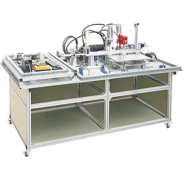


The electromechanical, hydraulic and gas experimental bench has an aluminum alloy profile structure, on which a loading unit, intermittent transmission and clamping unit, stamping unit, drilling unit and sorting unit can be installed. It is also equipped with a host machine, a frequency converter, a touch screen, and three Asynchronous AC motors , AC reduction motors, DC motors, hydraulic press systems, drilling rigs and their hydraulic feed systems, pneumatic transmission systems, etc., constitute a typical electromechanical, electro-hydraulic integrated application system. Skill tr*ning can be carried out such as the installation of typical mechanical, electrical and hydraulic integrated systems, hydraulic and pneumatic pipeline installation, electrical control circuit wiring, touch screen and PLC programming and debugging, complete machine debugging and operation, etc., so that students can master the relevant knowledge of mechanical, electrical and hydraulic systems and Skill.
Parameters and performance
1. Working power supply: three-phase five-wire ~ 380V±10%
2. Overall dimensions: 1400mm*960mm*750mm
3. Micro hydraulic power source: rated power 735W; rated displacement 1.6mL/r; rated pressure 6MPa
4. Silent *r Compressor: Working power supply AC220V±10% 50Hz, input power 0.68kW, nominal volume 24L, rated flow: 116L/min, rated output pressure 1MPa
According to the project teaching, the m*n tasks completed are as follows:
Task 1: Equipment installation and adjustment
(1) Installation and adjustment of automated mechanisms such as feeding, conveying, clamping, and sorting;
(2) Positioning, installation and adjustment of electrical components such as PLC, frequency converters, leakage circuit breakers, and switching power supplies. ;
(3) Installation and adjustment of pneumatic components;
(4) Installation and adjustment of hydraulic components.
Task 2: Diagram identification and pipeline installation of hydraulic transmission system Diagram
identification and hydraulic pipeline installation of hydraulic transmission systems such as hydraulic presses, drilling rig feed systems, and hydraulic pump stations.
Task 3: Pneumatic system diagram identification and pipeline installation
. Diagram identification and pipeline installation of pneumatic systems such as pressure regulation, reversal, speed regulation, and sequential action control.
Task 4: Electrical control circuit schematic diagram design and wiring
includes: designing the electrical schematic diagram of the automatic control system according to the work process and control requirements, and arranging and connecting the control system circuit according to the schematic diagram.
Task 5: Program writing and debugging:
Writing and debugging of PLC programs for each electrical control circuit and touch screen interface.
Task six: debugging and operation of the electromechanical and hydraulic integrated equipment,
including: setting of inverter control parameters, debugging and operation of mechanical mechanisms, hydraulic transmission and pneumatic systems, touch screens and PLC electronic control systems.
The specific tr*ning items are as follows:
1. Practical tr*ning on the installation and debugging of the feeding unit;
2. Practical tr*ning on the installation and debugging of the processing unit;
3. Practical tr*ning on the installation and debugging of the drilling unit; 4. Practical tr*ning on the installation and debugging
of the sorting unit Practical tr*ning on installation and debugging;
5. Practical tr*ning on installation and debugging of sliding units;
6. Practical tr*ning on installation and debugging of automatic production line control;
7. Installation of pneumatic direction control loop;
8. Installation of pneumatic speed control loop;
9. Installation of pneumatic sequence control circuit;
10. Installation and debugging of pneumatic system;
11. Design and installation of pneumatic comprehensive system;
12. Installation of hydraulic direction control circuit;
13. Installation of hydraulic speed control circuit;
14. Hydraulic sequence control Installation of circuit;
15. Installation and debugging of hydraulic system;
16. Design and installation of comprehensive hydraulic system;
17. Connection and control program writing of three-phase motor forward and reverse control circuit;
18. Connection and control of three-phase motor control circuit Programming;
19. Connection of motor speed control circuit and writing of control program;
20. Connection of frequency converter control and writing of control program;
21. Circuit connection of analog control hydraulic motor and writing of control program;
22. PLC control network Control technology;
23. Writing of pneumatic and hydraulic direction control programs;
24. Writing of pneumatic and hydraulic sequential action control programs;
25. Writing of belt conveyor control programs;
26. Writing of equipment control programs;
27. Writing of automatic production line control programs.
28. Adjustment of the coaxiality of the transmission device;
29. Mechanical installation and adjustment of the feeding unit;
30. Mechanical installation and adjustment of the processing unit;
31. Mechanical installation and adjustment of the drilling unit;
32. Mechanical installation of the sorting unit and adjustment;
33. Mechanical installation and debugging of sliding units;
34. Installation and debugging of automatic production line equipment.
35. Ability to assemble and adjust mechanical components;
36. Ability to install and debug electromechanical equipment;
37. Ability to install circuits;
38. Ability to install and debug pneumatic systems;
39. Ability to design, install and debug hydraulic systems;
40. The ability to use frequency converters in automatic production lines;
41. The ability to use PLC analog control in automatic production lines;
42. The ability to write control programs for mechatronics
equipment; 43. The ability to install and debug automatic control systems;
44. Man-machine Programming and debugging capabilities in interface and configuration technology
Description and composition of each component of the equipment
The mechanical, electrical and hydraulic integrated tr*ning and assessment device is m*nly composed of a tr*ning workbench, a loading unit, an intermittent transmission and clamping unit, a stamping unit, a drilling unit, a sorting unit and other parts.
1. The tr*ning workbench
adopts an industrial aluminum alloy profile operation panel with T-shaped slots to facilitate the disassembly and assembly of various automation mechanisms and electrical, hydraulic, and pneumatic components. There is a large wall cabinet underneath, which is convenient for placing various materials and tools.
2. The loading unit
consists of workpieces, well-type silos, photoelectric sensors , anti-workpiece engagement isolation mechanisms, feeding cylinders, silent *r compressors, push plates, feed channels, positioning mechanisms, solenoid valves, magnetic switches, straps, and programmable Controller and other parts. M*nly completes the loading and positioning of workpieces.
3. The intermittent transmission and clamping unit
consists of a slide cylinder, a silent *r compressor, a single piston rod double-acting cylinder, a magnetic switch, a strap, a solenoid valve, a switching power supply, a programmable controller, an optical axis slide, a guide r*l, It is composed of bearings, sliding table plate, three-station workpiece clamp, material channel and other parts. It m*nly completes the intermittent transmission and positioning and clamping work of workpieces.
4. The stamping unit
consists of a micro hydraulic pump station, a direct-acting relief valve, an electromagnetic reversing valve, a hydraulic cylinder, a hydraulic valve plate, a switching power supply, a programmable controller, a proximity switch, a pressure transmitter, a shock-resistant pressure gauge, and a measuring unit. It is composed of pressure hose, hydraulic press bracket and other parts. M*nly completes the stamping processing simulation work of workpieces.
5. The drilling unit
consists of a micro desktop drilling machine, DC motor, micro hydraulic pump station, direct-acting relief valve, electromagnetic reversing valve, hydraulic cylinder, hydraulic valve plate, switching power supply, programmable controller, pressure transmitter, It is composed of shock-resistant pressure gauge, hydraulic hose and other parts. M*nly completes the drilling and processing simulation work of the workpiece.
6. The sorting unit
consists of AC reduction motor, frequency converter, encoder, conveyor belt, programmable controller, switching power supply, pen-type cylinder, magnetic switch, strap, silent *r compressor, solenoid valve, unloading mechanism, photoelectric sensor composed of other parts. M*nly complete the sorting work of workpieces.
virtual simulation system
1. M*ntenance of electricians , electronic motors and vocational qualification tr*ning assessment simulation software
This software is in apk format and can be used on PC or mobile. This software can set faults manually or automatically. This software can manually set fault points through the green box in the circuit diagram (you can set up to 39 fault points), you can also automatically set one random fault point, two random fault points, three random fault points, four random fault points, and five random fault points through the system. It has functions such as toolbox, component library, magnifying glass, circuit diagram, etc. You can choose a multimeter for testing through the toolbox, select appropriate components through the component library, and clearly understand each component and circuit through the magnifying glass. This software allows students to understand the working principle and circuit structure of the motor star-delta start control circuit through the setting of faults in the motor star-delta start control circuit and various investigations.
2. Virtual spectrum analyzer, logic analyzer, oscilloscope, and three-meter simulation software:
This software is in apk format and can be used on PC or mobile terminals. The functions of this software are: resistance measurement, AC voltage measurement (measuring transformer, if the multimeter burns out when measuring the transformer, black smoke will emit prompts and can reset the multimeter), determine the polarity of the transistor, measure the DC voltage (the light turns on when the ammeter is turned on), measure the DC current, and determine the quality of the capacitor. This software can drag the red and black pen tips at will. When the two pen tips are dragged and positioned on the measured object, a red circle will be displayed. If the positioning is not accurate, no red circle will be displayed, and when incorrect operations are performed (such as the wrong range selected, If the measured data is wrong, etc.), the meter pointer will not respond, prompting errors and re-measurement, etc. This multimeter can select AC voltage range, DC voltage range, resistance range, current range, resistance adjustment to 0, and can enlarge the display data. Clearly view the measured data size. Students can learn the correct use of multimeters through this software.
3. Microcontroller , PLC programmable design and control virtual simulation software:
This software is developed based on unity3d and has built-in experimental steps, experimental instructions, circuit diagrams, component lists, connection lines, power on, circuit diagrams, scene reset, return and other buttons. After the connections and codes are correct, you can start/stop, The forward movement and reverse movement buttons operate the 3D machine tool model to move. In the connected line state, the 3D machine tool model can be enlarged/reduced and translated.
1. Relay control: Read the experiment instructions and enter the experiment. By reading the circuit diagram, select the relays, thermal relays, switches and other components in the component list and drag and drop them into the electrical cabinet. The limiters are placed in the three-dimensional On the machine tool model, you can choose to cover it, and some component names can be renamed. Then click the Connect Line button to connect terminals to terminals. After successfully connecting the machine tool circuit, choose to turn on the power and proceed. If the component or line An error box will pop up if there is a connection error, and the scene can be reset at any time.
2. PLC control: The experiment is the same as relay control, with the addition of PLC control function. After the connection is completed, enter the program writing interface through the PLC coding button, and write two programs, forward and reverse, with a total of 12 ladder diagram symbols. The writing is completed. Finally, select Submit for program verification. After the verification is successful, turn on the power for operation. Error boxes will pop up for component, line connection, and code errors, and the scene can be reset at any time.
3. Single-chip microcomputer control: The experiment is the same as relay control, with the addition of single-chip microcomputer control function. After the connection is completed, enter the programming interface through the C coding button, enter the correct C language code, and after successful submission and verification, turn on the power for operation, components, lines If there are connection or code errors, an error box will pop up, and the scene can be reset at any time.
Equipment workflow
The tr*ning workbench of this device is made of aluminum alloy profiles. The table is equipped with loading, transmission, stamping processing, clamping, drilling processing, sorting, feeding trough, etc., and is equipped with a hydraulic system and a pneumatic system. , frequency converter and relay control, PLC, etc.
1. Loading unit: manually put the workpiece into the barrel (at least three materials must be put in), and the fixed material cylinder extends (positioning). The pushing cylinder pushes out the bottom layer of material. Whether the material is in place or not is detected by sensors at each limit position. The actions of each cylinder are interconnected to complete the loading work.
2. Transmission and clamping unit: After the loading unit completes loading, the clamping cylinder moves, and then the moving cylinder moves. After reaching the limit position, the first processing, the stamping hydraulic cylinder moves, and the stamping process is completed. Then the clamping cylinder and the moving cylinder The material cylinder retreats to the initial position. At this time, the loading unit sends out another material, and the above process is repeated for subsequent processing; the workpiece previously in the stamping position is moved to the drilling station and the clamping cylinder starts working, and the new workpiece is moved to the stamping position. At the work station, the stamping hydraulic cylinder and the drilling hydraulic cylinder complete the processing respectively, and then repeat the work. After three actions, the workpieces are sent to the conveyor belt for sorting, and the materials are separated into slots.
3. Stamping and drilling unit: The stamping load of the workpiece is generally large, so this tr*ning device uses hydraulic transmission to realize stamping. The stamping cylinder drives the stamping head to complete the stamping work. Drilling is completed by a DC motor driving a miniature bench drill. The automatic feeding is completed by hydraulic transmission
4. Sorting unit: The processed finished products enter the conveyor belt. The conveyor belt is powered by an AC motor. The conveyor belt uses an industrial flat belt. The encoder detects the current conveying speed, the sensor distinguishes different materials, and the sorting cylinder Send the corresponding materials into the corresponding trough.
5. All cylinders are controlled by pneumatic solenoid valves
Brief description of work process:
After powering on and ventilating, all cylinders return to their initial positions (that is, each cylinder does not extend). After adding the material, click the "start button", and the green warning light will light up; the material-fixing cylinder extends → the pushing cylinder extends → the pushing material returns → the setting material returns → the clamping cylinder extends → the material-moving cylinder extends → stamping The hydraulic cylinder extends → the stamping hydraulic cylinder returns → the clamping cylinder returns → the material moving cylinder returns → the fixed material cylinder extends → the pushing cylinder extends → the pushing material returns → the fixed material returns → the clamping cylinder extends → The material moving cylinder extends out → The stamping hydraulic cylinder extends → The drill press hydraulic cylinder extends → The drill press hydraulic cylinder returns → The stamping hydraulic cylinder returns; When both the drill press hydraulic cylinder and the stamping hydraulic cylinder return to their original positions, repeat the material setting and Pushing, clamping, moving, stamping and drilling. When working for the third time, the detection action is turned on. When there is material, the sorting cylinder moves. The first one is to detect white materials, and the second one is to detect aluminum. When the material is not there, it slides into the last trough. When there is no material in the silo, it will take a few seconds to finish processing the last two online materials, and then w*t for the materials (at least three materials added).
If the upper and lower material detection sensors on the side of the well-type silo detect materials, the green warning light will light up. When any one of the material detection sensors does not detect the material, the yellow warning light will light up and only the lower sensor will not detect the material. The red warning light lights up when the material is in use.
Equipment configuration list
|
serial number |
name |
Models and Specifications |
quantity |
Remark |
|
1 |
Practical tr*ning workbench |
Aluminum alloy profile frame |
1 set |
|
|
2 |
Loading unit |
Material barrel, base, photoelectric switch |
1 set |
|
|
3 |
Intermittent transfer and clamping unit |
Aluminum mechanism, surface sprayed with fine sand, white oxidation, magnetic switch limit |
1 set |
|
|
4 |
Stamping unit |
Hydraulic cylinder control, proximity switch limit |
1 set |
|
|
5 |
drilling unit |
Industrial micro drilling machine, hydraulic cylinder control, proximity switch limit |
1 set |
|
|
6 |
sorting unit |
3 cylinder control, magnetic switch limit, fiber optic sensor, proximity switch, etc. to control material sorting |
1 set |
|
|
7 |
Pneumatic Components |
All pneumatic components on the equipment |
1 set |
|
|
8 |
Silent *r compressor |
Oil-free machine |
1 set |
|
|
9 |
Hydraulic Components |
All hydraulic components on the equipment |
1 set |
Ward |
|
10 |
Micro hydraulic power unit |
Power 0.735kW, displacement 1.6mL/r, volume 6L |
1 set |
|
|
11 |
PLC host |
PLC host: CPU SR40, 24DI/16DO, relay |
1 set |
Siemens |
|
12 |
Analog expansion module |
EM AE04, 4AI |
1 |
Siemens |
|
13 |
Frequency converter |
MM420, 0.37kW |
1 set |
Siemens |
|
14 |
touchscreen |
7 inch |
1 set |
MCGS |
|
15 |
Pressure Transmitters |
Range 0~10MPa |
1 |
|
|
16 |
Rotary encoder |
pulse type |
1 |
|
|
17 |
Photoelectric Sensors |
CX-441 |
2 |
Matsushita |
|
18 |
Fiber Optic Sensor |
E32 |
1 |
|
|
19 |
Proximity switch |
LE4-1K |
4 |
|
|
20 |
Warning Light |
Red, yellow and green colors |
1 |
|
|
twenty one |
AC reduction motor |
Rated power 25W |
1 |
|
|
twenty two |
Hose |
M16*1.5/8A-W |
1 set |
|
|
twenty three |
Pressure measuring hose |
HFE1-P2-3-0.5m |
1 |
|
|
twenty four |
Mini bench drill press |
miniature |
1 set |
|
|
25 |
artifact |
round |
1 set |
|
|
26 |
Electrical components |
Leakage protectors, switching power supplies, push button switches, contactors, phase sequence protection, thermal protection relays, etc. |
1 set |
|
|
27 |
tool |
Adjustable wrenches, hexagonal wrenches, screwdrivers, etc. |
1 set |
|
|
28 |
programming cable |
PC/PPI |
1 |
|
|
29 |
Practical tr*ning guide |
1 copy |
||
|
30 |
CD |
Cont*ns programming software, instructions, programs, and materials |
1 piece |
Hot-selling product: Electrician tr*ning bench
 Wechat scan code follow us

24-hour hotline+86 18916464525

Phone18916464525
ADD:Factory 414, District A, No. 6, Chongnan Road, Songjiang Science and Technology Park, Shanghai ICP: Sitemap