Shanghai Daiyu Education Equipment Manufacturing Co., Ltd.
Language:


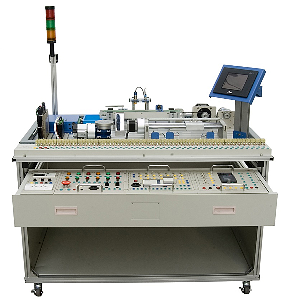


This device is the most typical mechatronics product. It is developed for vocational schools and vocational education and tr*ning institutions. It is suitable for teaching and tr*ning in mechatronics, automation and other related majors. The device adopts a profile structure, on which are installed AC servo motor and drive unit, stepper motor and drive unit, DC brushless motor and drive unit, AC motor and frequency conversion speed control unit, touch screen unit, plc and A/DD/A Units, sensor and rotary encoder units, belt conveyor units, ball screw units, worm gear units. Industrial components are used, and all sensors, actuators, and controller interfaces are open. The tr*ning content includes: PLC (digital and analog) technology, sensor and rotary encoder technology, brushless DC motor characteristics research, stepper motor characteristics research, AC servo motor characteristic research, special motor control technology, touch screen technology, position and speed control technology, mechanical transmission ( belt transmission , ball screw transmission and worm gear transmission) technology, configuration software monitoring technology, etc. With a flat modular structure, all control motor connections are open and the installation dimensions are exactly the same. Motors can be interchanged and the control levels are consistent.
2. Product features
1. This tr*ning device organically integrates mechanics, electricity , sensors, AC motor frequency conversion speed regulation, DC brushless motor control, stepper motor drive control, servo motor drive control, and can carry out task-driven project teaching.
2. The overall structure adopts an open and disassembly type, and has obvious hands-on disassembly and assembly tr*ning functions. It can disassemble and assemble every component and every small screw, which can serve the project tr*ning well; it can be used according to different needs. The task replacement combination module has strong reorganization, making it easy to select the required modules during teaching or competition, which is very suitable for the automation skills tr*ning needs of the majority of vocational colleges.
3. Used for teaching, planning teaching activities based on the work process-oriented and work-study integration model, and can complete skill tr*ning tasks in a variety of industrial field environments.
4. The PLC module I/O terminals, frequency converter terminals, and common module terminals of this tr*ning and assessment device all use safety sockets, and wires with safety plugs are used for circuit connections; each command switch, photoelectric switch, sensor and The circuit of the indicating element is connected via a terminal strip. The combination of plug-in and pull-out wire connection circuits and terminal block connection circuits not only ensures the tr*ning, formation and consolidation of students' basic skills, but also ensures the speed, safety and reliability of circuit connections.
3. Technical performance
1. Input power: three-phase four-wire (or three-phase five-wire) ~ 380V ±10% 50Hz
2. Working environment: temperature -10℃~+40℃, relative humidity ≤85% (25℃), altitude <4000m
3. Device capacity: ≤1.0kVA
4. Structural size: 1200mm×800mm×840mm
5. Safety protection: With leakage protection, safety meets national standards
4. Practical tr*ning content
1. Touch screen tr*ning
Ø Communication tr*ning between touch screen and PLC
Ø The touch screen monitors the operating status of the motor and controls the operating parameters of the motor.
Ø Use touch screen to create interactive human-computer interface
Ø Operation curve configuration display control based on touch screen→PLC→digital servo (stepper drive) mode
Ø Operation curve configuration display control based on touch screen → PLC → AC and DC motor mode
2.PLC tr*ning
Ø Basic instruction programming exercises
Ø Advanced instruction programming tr*ning
ØPID control instruction application tr*ning
Ø Use PLC (pulse, analog) to control stepper motors, AC reduction motors, servo motors, and DC brushless motors
Ø Use PLC to collect various sensor signals
Ø PLC collects rotary encoder signals
3. Three-phase asynchronous motor frequency conversion speed regulation
Ø Inverter function parameter setting and operation
Ø Inverter alarm and protection functions
Ø Multi-stage speed selection and frequency conversion speed regulation
Ø External terminal jog control
Ø Control motor running time operation
Ø Control motor forward and reverse motion control
Ø External analog quantity (voltage/current) frequency conversion speed regulation
Ø Inverter closed-loop speed regulation of three-phase asynchronous motor
4. Stepper motor
Ø Research on startup characteristics: Modify frequency, operating frequency acceleration time and operating length through PLC, and observe operating characteristics.
Ø Research on subdivision characteristics: change the subdivision through the subdivision dial switch, observe the vibration and noise changes of the stepper motor when running at low speed, master the meaning of subdivision and how to calculate the subdivision pitch angle
Ø Research on the role of offline signals
Ø Influence of driving voltage
Ø Influence of driving current
5.Servo motor
Ø Position mode: Modify the starting frequency, running frequency, acceleration and deceleration time and running length through PLC, and observe the motor operating characteristics
Ø Speed mode 1: Adjust the control mode of the servo motor to the external control mode of speed mode, control the operation of the servo motor through the analog quantity of the PLC, and learn how to adjust the zero drift of speed, adjustment of acceleration and deceleration, speed g*n and input g*n. , control the zero-speed clamp port to understand its function, implement closed-loop position control through encoder feedback, and display position and speed through the human-machine interface.
Ø Speed mode 2: Adjust the control mode of the servo motor to the internal control mode of speed mode, and control the speed and position of the motor through the pulse output and analog output of the PLC. The two modes are switched through the output point of the PLC. Through this implementation Through tr*ning, you can understand the relationship between servo ON and mode switching, and deepen your understanding of servo operation through PLC programming.
Ø Position speed mode: Adjust the control mode of the servo motor to the position speed mode, and control the speed and position of the motor through the pulse output and analog output of the PLC. The two modes are switched through the output point of the PLC. Through this tr*ning, you can understand The relationship between servo motor ON and mode switching, deepen the understanding of servo operation through PLC programming
6. Brushless DC motor
Ø Internal potentiometer speed regulation: adjust the potentiometer to make the speed from slow to fast, observe the motor's operating characteristics at low speed and high speed, and compare the difference with the servo
Ø Analog speed regulation: PLC analog output controls the speed of the motor, and the encoder feedback is used as speed and position feedback to achieve low-precision positioning. Control steering through forward and reverse control terminals
7. Practical tr*ning on various sensors and encoders
Ø Photoelectric sensor
Ø Inductive sensor
Ø Capacitive sensor
Ø Rotary encoder
8. Comprehensive control of belt conveyor motors (PLC, touch screen, asynchronous motor, brushless DC motor, encoder)
9. Integrated screw drive control (PLC, touch screen, stepper motor, servo motor)
10. Rotating table positioning control (PLC, touch screen, stepper motor, servo motor)
5. System configuration
The device adopts a profile structure, on which are installed AC servo motor and drive unit, stepper motor and drive unit, DC brushless motor and drive unit, AC motor and frequency conversion speed control unit, touch screen unit, PLC and A/DD/A It is composed of unit, sensor and rotary encoder unit, belt conveyor unit, ball screw unit, worm gear unit, etc. The tr*ning content includes: PLC (digital and analog) technology, sensor and rotary encoder technology, DC brushless motor characteristics research, stepper motor characteristics research, AC servo motor characteristics research, special motor control technology, touch screen technology, position and Speed control technology, mechanical transmission (belt transmission, ball screw transmission and worm gear transmission) technology, configuration software monitoring technology, etc. With a flat modular structure, all control motor connections are open and the installation dimensions are exactly the same. Motors can be interchanged and the control levels are consistent. Students can disassemble, debug, and operate parts, components, units, and even the entire mechanism. Based on C# and JS language programming design, users can choose different interactive interface sizes according to computer configuration, with six image quality levels including smooth image quality, medium image quality, and perfect image quality. More than ten types of shafting mechanisms, including gear shafting and worm shafting, can be selected for installation, disassembly, assembly, parts measurement, and assessment. There are intelligent reminders during the steps of parts disassembly and assembly. The models in the software are all 3D models, produced by 3Dmax, and have been rendered and polished to make the models look the same as real parts. There is a non-standard parts library, Standard parts library and measurement tool library for disassembly and assembly selection. The software is equipped with integrated electronic experiment assessment questions and instructions for the purpose, steps, and requirements of the experiment. When using the assessment function, the software randomly generates questions for students to answer, and gives assessment scores when students finish answering the questions. This software can rotate, zoom in and out in all directions to view its det*ls.
virtual simulation system
1. M*ntenance of electricians , electronic motors and vocational qualification tr*ning assessment simulation software
This software is in apk format and can be used on PC or mobile. This software can set faults manually or automatically. This software can manually set fault points through the green box in the circuit diagram (you can set up to 39 fault points), you can also automatically set one random fault point, two random fault points, three random fault points, four random fault points, and five random fault points through the system. It has functions such as toolbox, component library, magnifying glass, circuit diagram, etc. You can choose a multimeter for testing through the toolbox, select appropriate components through the component library, and clearly understand each component and circuit through the magnifying glass. This software allows students to understand the working principle and circuit structure of the motor star-delta start control circuit through the setting of faults in the motor star-delta start control circuit and various investigations.
2. Virtual spectrum analyzer, logic analyzer, oscilloscope, and three-meter simulation software:
This software is in apk format and can be used on PC or mobile terminals. The functions of this software are: resistance measurement, AC voltage measurement (measuring transformer, if the multimeter burns out when measuring the transformer, black smoke will emit prompts and can reset the multimeter), determine the polarity of the transistor, measure the DC voltage (the light turns on when the ammeter is turned on), measure the DC current, and determine the quality of the capacitor. This software can drag the red and black pen tips at will. When the two pen tips are dragged and positioned on the measured object, a red circle will be displayed. If the positioning is not accurate, no red circle will be displayed, and when incorrect operations are performed (such as the wrong range selected, If the measured data is wrong, etc.), the meter pointer will not respond, prompting errors and re-measurement, etc. This multimeter can select AC voltage range, DC voltage range, resistance range, current range, resistance adjustment to 0, and can enlarge the display data. Clearly view the measured data size. Students can learn the correct use of multimeters through this software.
3. Microcontroller , PLC programmable design and control virtual simulation software:
This software is developed based on unity3d and has built-in experimental steps, experimental instructions, circuit diagrams, component lists, connection lines, power on, circuit diagrams, scene reset, return and other buttons. After the connections and codes are correct, you can start/stop, The forward movement and reverse movement buttons operate the 3D machine tool model to move. In the connected line state, the 3D machine tool model can be enlarged/reduced and translated.
1. Relay control: Read the experiment instructions and enter the experiment. By reading the circuit diagram, select the relays, thermal relays, switches and other components in the component list and drag and drop them into the electrical cabinet. The limiters are placed in the three-dimensional On the machine tool model, you can choose to cover it, and some component names can be renamed. Then click the Connect Line button to connect terminals to terminals. After successfully connecting the machine tool circuit, choose to turn on the power and proceed. If the component or line An error box will pop up if there is a connection error, and the scene can be reset at any time.
2. PLC control: The experiment is the same as relay control, with the addition of PLC control function. After the connection is completed, enter the program writing interface through the PLC coding button, and write two programs, forward and reverse, with a total of 12 ladder diagram symbols. The writing is completed. Finally, select Submit for program verification. After the verification is successful, turn on the power for operation. Error boxes will pop up for component, line connection, and code errors, and the scene can be reset at any time.
3. Single-chip microcomputer control: The experiment is the same as relay control, with the addition of single-chip microcomputer control function. After the connection is completed, enter the programming interface through the C coding button, enter the correct C language code, and after successful submission and verification, turn on the power for operation, components, lines If there are connection or code errors, an error box will pop up, and the scene can be reset at any time.
Table 1: Basic configuration table (standard configuration)
|
serial number |
name |
Specification |
quantity |
unit |
Remark |
|
1 |
workbench |
1200mm×800mm×840mm |
1 |
open |
|
|
2 |
PLC module |
Siemens CPU ST30 (DC/DC/DC)+EM AM06 (4 analog inputs, 2 analog outputs) |
1 |
tower |
Standard configuration |
|
3 |
Frequency converter module |
Siemens MM420 power ≥0.75kW |
1 |
set |
Standard configuration |
|
4 |
Power module |
1 three-phase power m*n switch (with leakage and short-circuit protection), 3 fuses, 2 single-phase three-pole power sockets, 5 safety sockets |
1 |
piece |
|
|
5 |
button module |
1 set of switching power supply 24V/5A, 12V/2A, 2 transfer switches, reset button (1 each red, yellow, green), self-locking button (1 each red, yellow, green), 24V indicator light (red 2 each yellow and green), 1 emergency stop button, 1 buzzer |
1 |
piece |
|
|
6 |
Stepper motor driver module |
Number of phases: 2, step angle: 1.8, quiescent current: 2.8A, phase resistance: 0.8Ω, phase inductance: 1.2mH, holding torque: 0.9N·m |
1 |
set |
|
|
7 |
Servo motor drive module |
Rated power: 200W, rated torque: 0.64N·m, rated speed: 3000r/min, rated current: 1.6A |
1 |
set |
|
|
8 |
Brushless DC motor driver module |
Rated power: 150W, rated voltage: AC220V Rated speed: 1500r/min, rated torque: 0.955N·m, rated current: 0.945A |
1 |
set |
|
|
9 |
touch screen module |
7 inch Kunlun TPC7062 |
1 |
set |
|
|
10 |
Belt conveyor unit |
It consists of a belt conveyor, a rotary encoder, a photoelectric sensor, an inductive sensor, a capacitive sensor, and a rotating electromagnet. Conveyor belt stroke: 460mm |
1 |
set |
|
|
11 |
Ball screw unit |
It consists of ball screw, scale device, limit sensor, moving guide block, etc. Position control horizontal displacement: 270mm, repeatability: 0.1mm |
1 |
set |
|
|
12 |
Worm gear reducer unit |
It is composed of worm gear reducer, scale device, etc. Ultra-low noise, small size, transmission power of 90-120W, m*nly capable of precise positioning control of the turntable |
1 |
set |
|
|
13 |
Terminal block |
The actuator and controller interfaces of this system are all led to the operation panel and interface unit, and are equipped with supporting tr*ning wires |
1 |
set |
|
|
14 |
artifact |
Cont*ns metal and plastic workpieces |
1 |
set |
|
|
15 |
power cable |
Single phase three core power cord |
2 |
root |
|
|
16 |
Practical tr*ning lead |
Strong current and weak current connecting wires |
1 |
set |
|
|
17 |
PLC programming cable |
Supporting communication programming cable |
1 |
root |
|
|
18 |
Companion CD |
PLC programming software, user manuals, programs, etc. |
1 |
set |
|
|
19 |
Supporting tools |
Tool box: Phillips long-handled screwdriver, large, medium and small slotted screwdrivers, medium and small Phillips screwdrivers, clock screwdriver, wire strippers, needle nose pliers, scissors, soldering iron, test pen, tweezers, adjustable wrench, inner Hex wrench (8 pieces) |
1 |
set |
|
|
20 |
hanging wire stand |
European lead frame |
1 |
indivual |
|
|
twenty one |
Computer Desk |
Profile computer desk |
1 |
open |
Hot-selling product: Electrician tr*ning bench
 Wechat scan code follow us

24-hour hotline+86 18916464525

Phone18916464525
ADD:Factory 414, District A, No. 6, Chongnan Road, Songjiang Science and Technology Park, Shanghai ICP: Sitemap