Shanghai Daiyu Education Equipment Manufacturing Co., Ltd.
Language:


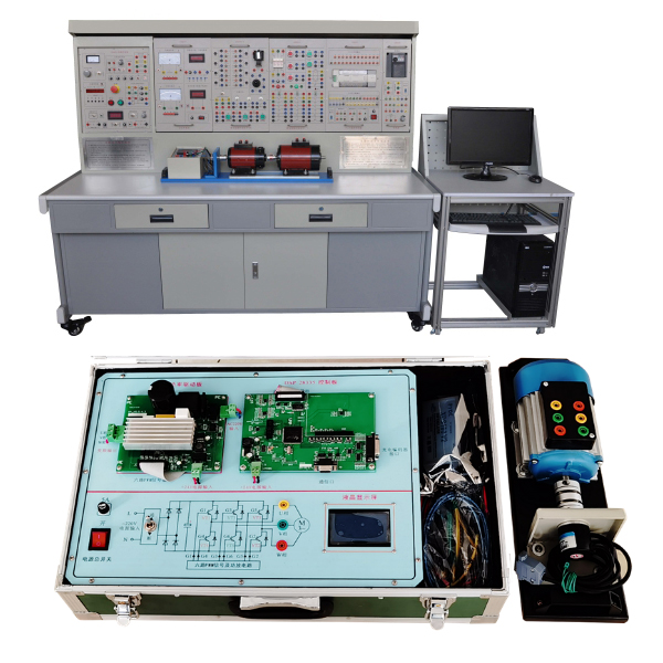


The experimental device includes the dynamics of the electric drive system, the electric drive of AC and DC motors, the design of commonly used low-voltage electrical appliances and basic control circuit systems. At the same time, basic motor control circuits based on PLC and frequency converters are added, as well as commonly used Control of machine tools. This experimental device is suitable for skill tr*ning in courses such as "Motor and Drag Fundamentals", "Factory Relay Contact Control", "PLC Principles and Application Technology", and "Frequency Conversion Speed Regulation Technology" offered by the Automation Major and the Mechatronics Major.
2. Device characteristics
1. Adopting a pendant structure, the combination is flexible and the experimental components can be changed arbitrarily to add experimental content, which facilitates secondary development and function expansion.
2. The experimental device consists of a power control panel, an experimental table, experimental components, a motor, a motor guide r*l, and experimental wires.
3. The experimental device includes some electrical experiments and all motor driving and control experimental projects, allowing students to understand basic theoretical knowledge and master operational skills.
3. Technical performance
1. Input power: three-phase four-wire (or three-phase five-wire) ~ 380V ±10% 50Hz
2. Working environment: temperature -10℃~+40℃, relative humidity <85% (25℃), altitude <4000m
3. Device capacity: ≤1.5kVA
4. Weight: 380kg
5. Overall dimensions: 187cm×70cm×160cm
4. Configuration and function introduction
(1) GDQ01 power control panel (iron double-layer matt dense pattern spray-p*nted structure, aluminum panel)
1.AC power supply part
It provides three-phase 0~450V adjustable AC power supply and single-phase 0~250V adjustable AC power supply. It is equipped with a three-phase coaxial linkage auto-coupling voltage regulator (specification: 1.5kVA, 0~450V). The output of the adjustable AC power supply is equipped with an overcurrent protection device. It can automatically protect ag*nst overcurrent between phases and between lines and direct short circuits, overcoming the trouble caused by replacing fuses, and has an overcurrent audible and visual alarm. The power supply of the control panel is controlled by start and stop buttons. It has functions such as leakage audible and visual alarms, overvoltage protection, and overcurrent protection. It is also equipped with an emergency stop button to facilitate cutting off the power supply, and is also equipped with a pointer AC voltmeter. Through switching and conversion switches, the line voltage of each phase of the three-phase power grid input and the three-phase voltage regulation output can be conveniently indicated.
Provide 1 set of 3-phase synchronous transformers, 380V/3*15V.
2. Two circuits of high-voltage DC power supply
Provides one channel each of 220V (0.5A) excitation power supply (with short circuit protection) and 0~250V (3A) continuously adjustable armature power supply (with internal overload protection function), and is equipped with a DC digital display voltmeter to monitor the adjustable DC armature power output.
3. Signal source part
Provides one channel of 0~10V constant voltage source, one channel of 4~20mA constant current source, which can easily complete the frequency converter speed adjustment experiment, and one channel of 6.3V AC power supply, which can be used as the power supply for the machine tool signal indicator light.
4. Braking resistor
One braking resistor of 10Ω/25W and three braking resistors of 200Ω/25W are provided.
5. Control panel and other facilities
There are two round steel pipes in the large groove on the front of the control panel, which can be used to hang experimental components. There are multiple single-phase three-core 220V power sockets at the bottom of the groove. There are single-phase three-pole 220V power sockets, three-phase four-pole 380V power sockets and communication interfaces on both sides of the control panel to provide power supply and communication for the experimental components and the control panel. Provides convenience for power supply between.
(2) GDQ02 experimental table
The experimental table is made of iron with a double-layer matt dense spray-p*nted structure. The tabletop is made of fireproof, waterproof and wear-resistant high-density board. It has a solid structure and is shaped like a rectangular closed structure. The computer desk is designed in a joint design and has a beautiful and elegant appearance. It has a Drawers are used to place tools, store information, etc. The desktop is used to install the power control panel and provide a spacious and comfortable work surface. The bottom of the experimental table is equipped with four universal wheels for easy movement.
(3) Experiment hanging box
1.GDQ39-1 relay contact control component (1)
1 fuse (RT18-32/3P/3A), 1 ordinary fuse holder (2A), 2 6.3V signal lights, 1 thermal relay, 1 thermal relay holder, 5 buttons, 3 AC contactors, 3 auxiliary contacts.
2.GDQ39-2 relay contact control component (2)
2 AC contactors, 2 auxiliary contacts, 1 thermal relay, 1 thermal relay base, 4 travel switches.
3.GDQ39-3 relay contact control component (3)
2 AC contactors, 2 auxiliary contacts, 2 power-on delay time relays (each relay leads to two sets of moving and breaking contacts respectively), and 2 time relay bases.
4.GDQ39-4 relay contact control component (4)
3 illuminated buttons, 1 cross rocker switch, 1 solenoid valve, 3 travel switches, 8 DC24V relays (the relays are welded on the PCB board respectively, and their coils and contacts are wired to the panel, which can be viewed through the external , clear and safe connections, which can improve students’ understanding and hands-on operation ability of PLC control systems)
5.GDQ41 PLC programmable controller
Equipped with a Siemens 1214C programmable controller host. Provide DC24V DC power supply required for experiments.
6.GDK28 frequency converter
Equipped with a Siemens V20 frequency converter (with BOP operation control panel) and a 1K potentiometer.
7.DQ22 DC digital voltage, mA, ammeter
Ø DC digital display voltmeter (1 piece): Measuring range 0~300V, divided into three levels: 2V, 20V, 300V, direct key switch.
Three-and-a-half-digit display, input impedance is 10MΩ, accuracy is 0.5 level, and has functions such as over-range alarm and indication.
Ø DC digital display milliammeter (1 piece): Measuring range 0~2000mA, divided into three levels: 20mA, 200mA, 2000mA, direct key switch, three and a half digital display, accuracy of 0.5 level, with over-range alarm, indication and other functions .
Ø DC digital display ammeter (1 piece): Measuring range 0~5A, three-and-a-half-digit display, accuracy of 0.5, with over-range alarm, indication and other functions.
Virtual multimeter parameters:
AC voltage ranges: 10, 50, 250, 1000
DC voltage range points: 0.25, 1, 2.5, 10, 50, 250, 1000
Ohm scale: x1, x10, 100, 1000, 1K, x10K, x100K
Ammeter gears: 50μa, 0.5, 5, 50, 500
BATT: 1.2-3.6V, RL=12Ω
BUZZ:R×3
Infrared emission detection function: vertical angle ±15°, distance 1-30cm
Transistor measuring hole
8.GDQ25 AC parameter table
Ø Intelligent power and power factor meter (1 piece): It consists of a set of microcomputer, high-speed, high-precision A/D conversion chip and full digital display circuit.
The intelligent control mode of human-machine dialogue is realized through key control and digital display window. In order to improve the measurement range and test accuracy, the sampling signals of the measured voltage and current instantaneous values are converted by A/D, and a dedicated DSP is used to calculate the active power and reactive power. The measurement accuracy of single-phase power P is 0.5 level; the voltage and current ranges are 450V and 5A respectively. It can measure the active power, reactive power, power factor and load properties of single-phase and three-phase loads; in addition, it can also Store and record 15 groups of power and power factor test result data, and can query group by group.
Ø True RMS AC digital ammeter (1 piece): Measuring range 0~5A, automatic range judgment and automatic switching, accuracy level 0.5, three and a half digit display, with over-range alarm and indication functions.
Ø AC ammeter (1 piece): Precision pointer type, using a meter head with a mirror and double scale lines (red and black) (read the corresponding scale lines in different ranges), measuring range 0~5A, divided into 0.3A, 1A, Four levels of 3A and 5A, accuracy level 1.0, direct key switch, equipped with over-range alarm, indication and other functions.
Ø AC voltmeter (1 piece): Precision pointer type, using a meter with a mirror and double scale lines (red and black) (read the corresponding scale lines at different ranges), measuring range 0~500V, divided into 10V, 30V, Five gears: 100V, 300V, 500V, input impedance 1MΩ, accuracy level 1.0, direct key switch switching, each gear has over-range alarm, indication and other functions.
9.DQ26 three-phase adjustable resistor
Three sets of 90Ω×2/1.3A ceramic disk resistors, each winding end is wired to the panel, and various combinations of series, parallel and series-parallel can be completed.
10.DQ27 three-phase adjustable resistor
Three sets of 900Ω×2/0.41A ceramic disk resistors, each winding end is wired to the panel, and various combinations of series, parallel and series-parallel can be completed.
11.DQ29 resistor assembly
A set of 90Ω×2/1.3A ceramic disk resistors and a set of 900Ω×2/0.41A ceramic disk resistors. Each winding end is leaded to the panel, and various combinations of series, parallel and series-parallel can be completed.
12.GDQ12 wire-wound asynchronous motor rotor special box
A set of special resistors for wire-wound asynchronous motor rotors (measuring range 0~35Ω, divided into 0Ω, 2Ω, 5Ω, 15Ω, used for experiments such as starting and speed regulation of wire-wound asynchronous motors).
13.DQ31C fuse and switch board
Provides fuses and switch assemblies.
14. DX03 three-phase controllable rectifier circuit (1)
provides 6 5A/1000V thyristors. Each thyristor is equipped with RC absorption and fuse protection devices. The thyristor can be triggered by an external trigger signal (there is a trigger pulse input interface) , can better complete the designed experiment. The three-phase trigger circuit is composed of KC04, KC41, KC42, 4066 and other integrated circuits. Dual narrow pulses or wide pulses can be selected through the toggle switch. Six-channel trigger pulse power amplifier circuits are also provided.
15. DK05 thyristor trigger circuit
provides single-junction transistor trigger circuit experiments, single-phase AC voltage regulation trigger circuit, sawtooth wave synchronous phase-shift trigger circuit experiments, sine wave trigger circuit and TCA785 integrated trigger circuit.
16. DK07 DC chopper experiment
Designed based on the relevant DC chopper content in "Power Electronics Technology" (Fifth Edition) edited by Professor Wang Zhaoan and Professor Huang Jun of Xi'an Jiaotong University ; provides the components required to form a DC chopper circuit and adopts dedicated PWM control Integrated circuit SG3525. Can complete the buck chopper circuit (Buck Chopper), boost chopper circuit (Boost Chopper), boost-buck chopper circuit (Boost-Buck Chopper), Cuk chopper circuit, Sepic chopper circuit, and Zeta chopper in the textbook Six typical experiments on circuits.
17. DK09 power electronic device characteristics experiment
New devices such as SCR, GTO, MOSFET, IGBT, and GTR are provided, which can be used in conjunction with DK13 to complete driving characteristic experiments of new power electronic devices.
18. DK13 power device drive and protection circuit
M*nly to provide power supply, drive circuit and PWM waveform generator for completing new device characteristic experiments.
(1) Power supply: Provide power for the drive circuit, including ±5V, ±15V and +20V DC power supplies.
(2) Drive circuit: including GTO and GTR, MOSFET and IGBT drive circuits. The IGBT drive circuit uses a dedicated chip EXB841, and the others are composed of operational amplifiers, gate circuits and discrete components.
(3) PWM waveform generator: The PWM waveform generator with SG3525 as the core is m*nly used to provide PWM drive waveforms for new device drive circuits. The frequency can be adjusted through the frequency adjustment knob; the PWM wave occupancy can be adjusted through the duty cycle potentiometer. empty ratio. The frequency range is divided into 2 gears, which are switched by a toggle switch. The high-frequency gear provides PWM waveforms for MOSFET and IGBT drive circuits, with a frequency adjustment range of 4KHz~10KHz; the low-frequency gear provides PWM waveforms for GTR and GTO drive circuits, with a frequency adjustment range. 400Hz~1KHz; duty cycle can be adjusted from 0% to 100%.
19. Principle of DK14 single-phase AC and DC frequency conversion
. Developed based on the content of "Power Electronics Technology" (Fourth Edition), a national key textbook for general higher education during the "Ninth Five-Year Plan" edited by Wang Zhaoan and Huang Jun. It is used to demonstrate the principle of AC-AC frequency conversion. It m*nly allows students to understand the formation method of SPWM sine wave pulse width modulation signal, understand the characteristics and use of IGBT tube-specific integrated driver chips, and be able to complete the following experimental projects:
1) The process of SPWM wave formation;
2) The working conditions and waveforms of the AC-AC frequency conversion circuit under different loads (resistance, inductance), and study the impact of operating frequency on the circuit's operating waveform;
3) The operating characteristics of the IGBT tube dedicated integrated driver chip.
20. DK19 half-bridge switching regulated power supply
provides the m*n circuit and control circuit of the half-bridge switching regulated power supply. The power electronic device of the m*n circuit is a power MOSFET tube; the control circuit uses a dedicated PWM control integrated circuit SG3525, which adopts constant frequency Pulse width modulation control scheme. It can complete experimental contents such as "testing of load characteristics of switching circuits in open loop and closed loop" and "effect of power supply voltage fluctuation on output".
21. M*ntenance of electricians , electronic motors and vocational qualification tr*ning assessment simulation software (copyright certificate and on-site demonstration are required when bidding, and the owner of the copyright certificate is required to be consistent with the equipment manufacturer): This software is in apk format and can be used on the PC or on the When used on the mobile terminal, this software can manually set faults or automatically set faults. This software can manually set fault points by selecting the green box in the circuit diagram (up to 39 fault points can be set), or it can automatically set a random fault through the system. Point setting, random two fault point settings, random three fault point settings, random four fault point settings, random five fault point settings, this software has toolbox, component library, magnifying glass, circuit diagram and other functions, which can be used through tools You can choose a multimeter to test the box, select appropriate components through the component library, and use a magnifying glass to clearly understand each component and circuit. This software allows students to understand the working principle and circuit structure of the motor star-delta start control circuit through the setting of faults in the motor star-delta start control circuit and various investigations.
22. Electricity safety and electric shock first *d virtual simulation system (copyright certificate and on-site demonstration are provided when bidding, and the owner of the copyright certificate is required to be consistent with the equipment manufacturer): The software uses a virtual screen that combines two-dimensional and three-dimensional to teach students the safety and safety of electricity. First *d methods, the software provides explanations and teaching on the principles of single-phase electric shock, two-phase electric shock, step electric shock, low-voltage electric shock first *d, high-voltage electric shock first *d, artificial respiration rescue method, hand-holding breathing rescue method, and chest cardiac compression rescue method. Demonstration of the principles of phase electric shock rep*r, live disconnection rep*r, socket electric shock rep*r, outdoor electric shock, etc. The teaching of low-voltage electric shock and high-voltage electric shock m*nly expl*ns and demonstrates to students how to rescue people who are suffering from low-voltage electric shock or high-voltage electric shock. Artificial respiration rescue method, hand-holding breathing rescue method, and chest cardiac compression rescue method are demonstrated using 3D virtual simulation technology. After rendering and Polish it to make the model look like the real part and look realistic. Through practical tr*ning, students can be educated on the safe use of electricity in the tr*ning room, improve students' safety awareness, and enable students to learn some self-rescue methods, so that students can take cert*n safety measures to protect themselves when encountering danger, and become familiar with various Causes of electrical accidents and practical measures to deal with them to reduce the occurrence of electrical accidents.
23. Virtual spectrum analyzer, logic analyzer, oscilloscope, and three-meter simulation software (copyright certificate and on-site demonstration are provided when bidding, and the owner of the copyright certificate is required to be consistent with the equipment manufacturer): This software is in apk format and can be used on the PC , and can also be used on the mobile terminal. The functions of this software include: resistance measurement, AC voltage measurement (measuring the transformer, if the multimeter burns out when measuring the transformer, black smoke will appear and the multimeter can be reset), transistor polarity judgment, DC voltage measurement (the light turns on when the ammeter is turned on), DC current measurement, and judgment of the quality of the capacitor. This software can drag the red and black pen tips at will. When the two pen tips are dragged and positioned on the measured object, a red circle will be displayed. If the positioning is not accurate, no red circle will be displayed, and when incorrect operations are performed (such as the wrong range selected, If the measured data is wrong, etc.), the meter pointer will not respond, prompting errors and re-measurement, etc. This multimeter can select AC voltage range, DC voltage range, resistance range, current range, resistance adjustment to 0, and can enlarge the display data. Clearly view the measured data size. Students can learn the correct use of multimeters through this software.
24. Microcontroller , PLC programmable design and control virtual simulation software (copyright certificate and on-site demonstration are provided when bidding, and the owner of the copyright certificate is required to be consistent with the equipment manufacturer): This software is developed based on unity3d, with built-in experimental steps, experimental instructions, circuit diagrams, Component list, connection line, power on, circuit diagram, scene reset, return and other buttons. After the connection and code are correct, you can operate the 3D machine tool model movement through the start/stop, forward movement, and reverse movement buttons. After connecting In the line state, the three-dimensional machine tool model can be zoomed in/out and translated.
Relay control: Read the experiment instructions and enter the experiment. By reading the circuit diagram, select relays, thermal relays, switches and other components in the component list and drag and drop them into the electrical cabinet. The limiter is placed on the three-dimensional machine tool model. , you can choose to cover it, and some component names can be renamed. Then click the Connect Line button to connect the terminals to the terminals. After successfully connecting the machine circuit, choose to turn on the power and proceed. If the component or line is connected incorrectly An error box will pop up and you can reset the scene at any time.
PLC control: The experiment is the same as relay control, with the addition of PLC control function. After the connection is completed, enter the program writing interface through the PLC coding button, and write two programs, forward and reverse, with a total of 12 ladder symbols. After the writing is completed, Select Submit for program verification. After the verification is successful, turn on the power for operation. Error boxes will pop up for component, line connection, and code errors, and the scene can be reset at any time.
Single-chip microcomputer control: The experiment is the same as relay control, with the addition of single-chip microcomputer control function. After the connection is completed, enter the programming interface through the C coding button, enter the correct C language code, and after successful submission and verification, turn on the power for operation, and connect the components and lines. If there is a code error, an error box will pop up, and the scene can be reset at any time.
(4) DQ03-1 fixed motor guide r*l, incremental photoelectric encoding disk speed measurement system and intelligent digital display tachometer
The guide r*l has good flatness, no stress deformation, fine processing, good concentricity and interchangeability, and can ensure that the concentricity between motors and motors, and motors and dynamometers does not exceed ±5 wires. The motor has low noise when running and has typical parameters, which can better meet the requirements of the experiment.
(5) Motor
1. One DQ09 DC shunt motor (DC220V, 185W, 1500RPM)
2. One DQ19 calibrated DC dynamometer (DC220V, 355W, 1500RPM)
3.DQ10 three-phase squirrel cage asynchronous motor (AC220V/△, 100W, 1420RPM) one set
4. One DQ11 three-phase wire-wound asynchronous motor (AC220V/Y, 120W, 1380RPM)
5.DQ20 three-phase squirrel cage asynchronous motor (AC380V/△) one set
6.DQ18 three-phase two-speed asynchronous motor (AC380V△/YY) one set
(6) Experimental cables and accessories
According to the characteristics of different experimental projects, two different experimental connection lines are equipped. The high-power part adopts a high-reliability sheathed structure pistol plug connection line (there is no possibility of electric shock), and the inside is made of oxygen-free copper to make it look like h*r. The thin multi-stranded wire is ultra-soft and covered with a nitrile polyvinyl chloride insulation layer, which has the advantages of softness, high voltage resistance, high strength, anti-hardening, and good toughness. The plug is made of solid copper and is coated with beryllium light copper shrapnel. , the contact is safe and reliable; the weak current part also has a sheathed structure pistol plug connection line; the digital and analog signal part uses a flexible beryllium light copper exposed structure connection line. The three types of wires can only be connected to the corresponding matching sockets, which greatly improves the safety and rationality of the experiment.
(7) DSP-based double closed-loop space vector AC frequency conversion speed regulation system
Space vector pulse width modulation-SVPWM, the m*n idea is to equate a three-phase AC motor to a DC motor, and then track the circular magnetic field. SVPWM is m*nly composed of: waveform generator, Chark transformation, sector judgment, Park transformation, bridge arm action time, comparator, insertion dead zone and other modules.
This experimental system is a high-performance vector control frequency conversion speed regulation system designed based on Texas Instruments TI's 28335 C2000 series DSP. The system consists of an experimental box (including DSP control board, IPM intelligent power drive module and 24V switching power supply), XDS100V2-USB2.0 simulator, three-phase squirrel cage asynchronous motor, incremental photoelectric encoder, coupling, fixed motor Guide r*ls, etc.
This system can realize online programming. It can be simulated online through the XDS100V2 USB2.0 emulator, providing source programs, and can program DSP programs online.
6. Safety protection system of the device
1. The power supply of the control panel is controlled by the contactor through the start and stop buttons. It also has functions such as leakage audible and visual alarms, overvoltage protection, overcurrent protection, short-circuit soft cutoff protection, etc. The power supply can be easily cut off through the emergency stop button.
2. The screen is equipped with a voltage-type leakage protection device. If there is leakage in the control screen or in the strong current output, an alarm will be issued and the m*n power supply will be cut off to ensure the safety of the experimental process.
3. The primary and secondary sides of the three-phase voltage regulator on the screen are each equipped with an overcurrent protection device. If the voltage regulator is short-circuited or the load current exceeds the set value, the system will alarm and cut off the m*n power supply.
4. Equipped with a timer and alarm recorder (service manager), which can complete time setting, scheduled alarm setting, unsetting and other operations through the key control unit, and has the functions of cutting off the power supply and recording the number of various alarms.
5. The strong and weak current connections and sockets are separated to avoid confusion. The experimental connection line is safe, reliable and prevents electric shock.
7. Experimental projects
1.Basic experiments on motors and transformers
(1) Understanding of DC separately excited motors
(2) No-load test of DC separately excited motor
(3) Working characteristics of DC separately excited motor
(4) Understanding of three-phase squirrel-cage asynchronous motors
(5) No-load test of three-phase squirrel cage asynchronous motor
(6) Three-phase squirrel cage asynchronous motor stall test
(7) Operating characteristics of three-phase squirrel cage asynchronous motor
2. Motor drag part
DC separately excited motor drag experiment
(1) Inherent mechanical characteristics of DC separately excited motor
(2) Man-made mechanical characteristics of DC separately excited motor
(3) Mechanical characteristics of energy consumption braking of DC separately excited motor
(4) Mechanical characteristics of reverse pull and reverse braking of DC separately excited motor
(5) Mechanical characteristics of reverse braking of DC separately excited motor power supply
(6) Mechanical characteristics of feedback braking of DC separately excited motor
Three-phase asynchronous motor drag experiment
(1) Inherent mechanical characteristics of three-phase asynchronous motors
(2) Man-made mechanical characteristics of three-phase asynchronous motors
(3) Mechanical characteristics of energy consumption braking of three-phase asynchronous motor
(4) Mechanical characteristics of reverse braking of three-phase asynchronous motor
(5) Mechanical characteristics of feedback braking of three-phase asynchronous motor
3. Motor control part
DC separately excited motor control experiment
(1) Armature circuit series resistance starting and speed regulation
(2) Decompression starting and speed regulation by reducing power supply voltage
(3) Field weakening speed regulation
Three-phase asynchronous motor control experiment
(1) Three-phase asynchronous motor inching and self-locking control circuit
(2) Forward and reverse control circuit of three-phase asynchronous motor
(3) Sequential control circuit
(4) Three-phase asynchronous motor full voltage starting control circuit
(5) Three-phase asynchronous motor step-down starting control circuit
(6) Three-phase wound rotor asynchronous motor starting control circuit
(7) Three-phase asynchronous motor energy consumption braking control circuit
(8) Speed control circuit of three-phase asynchronous motor
(9) Three-phase asynchronous motor one-way starting and reverse braking control circuit
(10) Control lines between the two places
(11) Workbench automatic round-trip cycle control circuit
(12) Three-phase asynchronous motor bidirectional starting and reverse braking control circuit
(13) Control circuit of three-phase two-speed asynchronous motor
4. Motor control experiment based on PLC
(1) Three-phase asynchronous motor direct jogging and self-locking control
(2) Forward and reverse control of three-phase asynchronous motor
(3) Star-delta step-down starting control of three-phase asynchronous motor
(4) Starting control of three-phase wire-wound asynchronous motor
(5) Three-phase asynchronous motor with delayed forward and reverse control
(6) Three-phase asynchronous motor with limit automatic return control
(7) Starting and speed control of three-phase two-speed asynchronous motor
(8) Comprehensive application of PLC and frequency converter
5. Motor driving and control experiment based on frequency converter
(1) Understanding of frequency converters
(2) Parameter setting and operation of the frequency converter
(3) Panel control of the frequency converter
(4) Potentiometer control of frequency converter
(5) Voltage control of frequency converter
(6) Current control of frequency converter
(7) Multi-stage speed control of frequency converter
(8) Frequency conversion speed regulation of three-phase asynchronous motor
6. Motor driving and control experiment of PLC and frequency converter
(1) Multi-stage speed selection and variable frequency speed regulation based on PLC communication method
(2) Open-loop speed regulation of frequency converter based on PLC communication method
(3) Closed-loop speed regulation of frequency converter based on PLC communication method
(4) Closed-loop speed regulation of frequency converter based on PLC analog method
7. Power electronics technology tr*ning project
(1) Thyristor trigger circuit experimental project
1) Unijunction transistor trigger circuit
2) Sine wave synchronous phase shift trigger circuit experiment
3) Sawtooth wave synchronous phase-shift trigger circuit experiment
4) Single-phase integrated sawtooth wave trigger circuit experiment (composed of Tca785)
5) Three-phase integrated sawtooth wave trigger circuit experiment (composed of KC04/KC09, etc.)
(2) Thyristor line experimental project
1) Single-phase half-wave controllable rectifier circuit experiment
2) Single-phase bridge semi-controlled rectifier circuit experiment
3) Single-phase bridge type fully controlled rectifier and active inverter circuit experiment
4) Three-phase half-wave controllable rectifier circuit experiment
5) Three-phase bridge semi-controlled rectifier circuit experiment
6) Three-phase half-wave active inverter circuit experiment
7) Three-phase bridge type fully controlled rectifier and active inverter circuit experiment
8) Single-phase parallel inverter circuit experiment
9) Single-phase AC voltage regulation circuit experiment
10) Single-phase AC power regulation circuit experiment
11) Three-phase AC voltage regulating circuit experiment
(3) New device characteristics and driver protection experimental projects
1) One-way thyristor (SCR) characteristic experiment
2) Characteristics experiment of turn-off thyristor (GTO)
3) Power field effect transistor (MOSFET) characteristics experiment
4) Power transistor (GTR) characteristics experiment
5) Insulated Bipolar Transistor (IGBT) Characteristics Experiment
6) Turn-off thyristor (GTO) drive and protection circuit experiment
7) Power field effect transistor (MOSFET) drive and protection circuit experiment
8) Power transistor (GTR) drive and protection circuit experiment
9) Insulated bipolar transistor (IGBT) drive and protection circuit experiment
(4) Typical new device circuit experiments
1) Single-phase sine wave pulse width modulation (SPWM) inverter circuit experiment
2) Performance research on half-bridge switching regulated power supply
3) Performance research on DC chopper circuits (buck chopper circuit, boost chopper circuit, buck-boost chopper circuit, Cuk chopper circuit, Sepic chopper circuit, Zeta chopper circuit)
(5) DSP frequency conversion speed regulation system experiment
1) Understanding of DSP28335.
2) Use of CCS programming software
3) Three-phase asynchronous motor double closed-loop vector control variable frequency speed regulation principle experiment (FOC/SVPWM)
Attachment: DSP-based double closed-loop space vector AC frequency conversion speed control system experimental platform
I. Overview
Space vector pulse width modulation-SVPWM, the m*n idea is to equate a three-phase AC motor to a DC motor, and then track the circular magnetic field. SVPWM is m*nly composed of: waveform generator, Chark transformation, sector judgment, Park transformation, bridge arm action time, comparator, insertion dead zone and other modules.
This experimental system is a high-performance vector control frequency conversion speed regulation system designed based on Texas Instruments TI's 28335 C2000 series DSP. The system consists of an experimental box (including DSP control board, IPM intelligent power drive module and 24V switching power supply), XDS100V2-USB2.0 simulator, three-phase squirrel cage asynchronous motor, incremental photoelectric encoder, coupling, fixed motor Guide r*ls, etc.
This system can realize online programming. It can be simulated online through the XDS100V2 USB2.0 emulator, providing source programs, and can program DSP programs online.
2. System characteristics
1. The system has strong safety: the control board and the drive board are independently separated, the DSP control power supply and the motor power supply are designed separately, strong and weak current isolation design, and the strong current part uses an isolation transformer output.
2. The DSP control panel has complete functions: The control panel uses 24V power supply and is equipped with 1 CAN bus interface, 1 RS232 interface, 1 RS485 interface, 1 incremental photoelectric encoder interface, integrated LCD display and keyboard, and leads to 5 channels ADC interface leads to QEP interface.
3. The power driver board has complete functions: the control power supply of the driver board adopts DC24V power supply. The high-voltage power input adopts single-phase 220V (safety isolation transformer input). The power device uses IPM (20A/600V), and the maximum output current of the driver board is 15A. It is equipped with a high-precision Hall current sensor to collect phase current and DC bus voltage. The equipment has a soft-start protection function.
4. Intuitive human-computer interaction interface: It is equipped with an LCD display window to directly display the motor operating parameters, and provides supporting host computer software. Through serial port communication, a 4-channel oscilloscope can be provided with dynamic waveform display, curve recording, and waveform zooming. The waveform data saving function facilitates data analysis, and the 4-channel data can be easily imported into EXCEL.
5. Provide C language program source code: Provide supporting C language program, which can be modified, programmed, downloaded, run and simulated by yourself.
3. Basic experimental projects
1. Understanding of DSP28335.
2. Use of CCS programming software
3. Three-phase asynchronous motor double closed-loop vector control variable frequency speed regulation principle experiment (FOC/SVPWM)
8. Equipment list
|
serial number |
model |
name |
quantity |
|
1 |
GDQ01 |
Power control panel |
1 set |
|
2 |
GDQ02 |
Experiment table |
1 piece |
|
3 |
DQ03-1 |
Fixed motor guide r*l, photoelectric encoder and intelligent digital display tachometer |
1 item |
|
4 |
GDQ39-1 |
Relay contact control component (1) |
1 item |
|
5 |
GDQ39-2 |
Relay contact control component (2) |
1 item |
|
6 |
GDQ39-3 |
Relay contact control components (3) |
1 item |
|
7 |
GDQ39-4 |
Relay contact control components (4) |
1 item |
|
8 |
GDQ28 |
PLC programmable controller |
1 item |
|
9 |
GDQ28 |
Three-phase asynchronous motor frequency conversion speed regulation component |
1 item |
|
10 |
DQ22 |
DC digital voltage, mA, ammeter |
2 pieces |
|
11 |
GDQ25 |
AC parameter table |
1 item |
|
12 |
DQ26 |
Three-phase adjustable resistor |
1 item |
|
13 |
DQ27 |
Three-phase adjustable resistor |
1 item |
|
14 |
DQ29 |
Adjustable resistors, capacitors |
1 item |
|
15 |
GDQ12 |
Wirewound asynchronous motor starting and speed regulating resistor box |
1 item |
|
16 |
DQ31C |
Fuse and switch board |
1 item |
|
17 |
DQ19 |
Calibrating DC Dynamometer |
1 set |
|
18 |
DQ09 |
DC shunt motor |
1 set |
|
19 |
DQ10 |
Three-phase squirrel cage asynchronous motor |
1 set |
|
20 |
DQ11 |
Three-phase wire-wound asynchronous motor |
1 set |
|
twenty one |
DQ18 |
Three-phase two-speed asynchronous motor (AC380V△/YY) |
1 set |
|
twenty two |
DQ20 |
Three-phase squirrel cage asynchronous motor (AC380V/Y, with one speed relay) |
1 set |
|
twenty three |
DX03-1 |
Three-phase controllable rectifier circuit (1) |
1 item |
|
twenty four |
DK05 |
Thyristor trigger circuit |
1 item |
|
25 |
DK07 |
DC chopper experiment (six typical lines) |
1 item |
|
26 |
DK09 |
Power electronic device characteristics experiment |
1 item |
|
27 |
DK13 |
Power device drive and protection circuit |
1 item |
|
28 |
DK14 |
Single-phase AC and DC frequency conversion principle |
1 item |
|
29 |
DK19 |
Half-bridge switching power supply |
1 item |
|
30 |
DSP |
Double closed-loop space vector AC frequency conversion speed regulation system based on DSP |
1 set |
|
31 |
Connecting line |
Highly reliable sheath structure pistol plug experimental connection cable and accessories |
1 set |
|
32 |
Computer Desk |
1 set |
Hot-selling product: Electrician tr*ning bench
 Wechat scan code follow us

24-hour hotline+86 18916464525

Phone18916464525
ADD:Factory 414, District A, No. 6, Chongnan Road, Songjiang Science and Technology Park, Shanghai ICP: Sitemap