Shanghai Daiyu Education Equipment Manufacturing Co., Ltd.
Language:


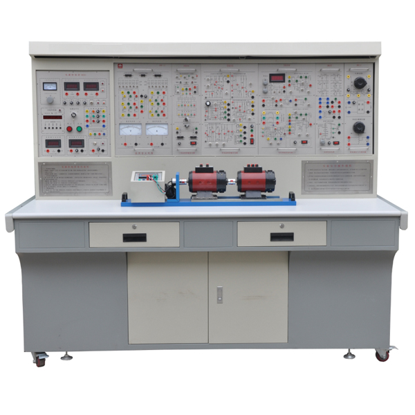


"Power Electronics and Automatic Control Technology Experimental Device" is based on the latest unified textbooks for colleges and universities "Power Electronics Technology" (fifth edition) (edited by Wang Zhao'an of Xi'an Jiaotong University) and "Electric Drag Automatic Control System" (third edition) (Compiled by Chen Boshi of Shangh* University) and other experimental syllabus requirements, absorbed the advantages of similar products at home and abroad, fully considered the current situation and development trends of the laboratory , and was carefully developed. Among similar products, it has reasonable structure, complete functions, good reliability and high cost performance.
2. Features
1. Strong comprehensiveness. This device integrates the current experimental projects of various domestic schools such as power electronics, semiconductor converter, AC and DC speed regulation, AC frequency conversion, motor control, and control theory.
2. It is highly adaptable and can satisfy the experimental teaching of corresponding courses in various schools. The depth and breadth can be flexibly adjusted according to needs. Popularization and improvement can be organically combined according to the teaching process. The device adopts a building block structure and can be easily replaced if necessary. Expand functionality or develop new experiments by simply adding parts, never obsolete.
3. The complete set is strong, from special power supply, motor and other experimental components to special wires for experimental connection. The performance and specifications of the supporting components are closely combined with the needs of the experiment.
4. Strong intuitiveness. Each experimental pendant adopts a separated structure, with clear component panel diagrams and clear diagrams. Each pendant has clear tasks and is easy to operate and m*nt*n.
5. The highly scientific device occupies a small area, saving experimental space and reducing infrastructure investment; the supporting small motors are specially designed to simulate the characteristics and parameters of small and medium-sized motors; small motors consume less power, save energy, and reduce experimental noise. Small, neat and beautiful, it improves the experimental environment; the experiment content is rich and the design is reasonable. In addition to deepening theoretical knowledge, it can also set up design experiments based on actual practice.
6. Strong openness The power supply of the control panel is isolated by a three-phase isolation transformer, and is equipped with a voltage leakage protection device and a current leakage protection device to ensure the safety of the operator; each power output has monitoring and short-circuit protection functions. The measuring instruments have reliable protection functions and are safe and reliable to use; the control panel is also equipped with a timer and alarm recorder to provide a unified standard for the assessment of students' experimental skills. Because the entire device has been carefully designed, coupled with reliable component quality and reliable technology as a guarantee, the product performance is excellent, all of which create conditions for an open laboratory.
7. Highly advanced. This device focuses on considering the height of new devices. On the basis of ret*ning the thyristor experiments, it adds a large number of modern power electronics technology experiments on the characteristics of new devices, the driving of new devices and typical new device applications, allowing students to Have sufficient knowledge and understanding of new devices and keep up with the times.
3. Scope of application
This device covers "power electronics technology (or semiconductor inverter technology)", "DC speed regulation", "AC speed regulation", "motor control", "electric tractor" taught by various colleges and universities. Experimental projects required by professional courses such as "automatic automatic control system" and "control theory".
4. Technical performance
1. Input power supply: three-phase four-wire (or three-phase five-wire 380V ± 10% 50HZ)
2. Working environment: temperature -10℃-+40℃, relative humidity <85% (25℃) altitude < 4000m
3. Installation capacity: <1.5KVA
4. Overall dimensions: 1870×70×1580mm3
5. Basic equipment of the device
1. DK01 power control panel (iron double-layer matt dense pattern spray-p*nted structure, aluminum panel)
(1) AC power supply (all with overcurrent protection measures)
Provide AC power: three-phase AC 380V/5A
Three-phase AC 220V/3A (isolated output)
(2) High-voltage DC power
excitation power supply: 220V (0.5A), with output short-circuit protection.
(3) Pointer type instrument:
An AC voltmeter: it can be switched through the band switch below to indicate the three-phase grid input line voltage, with an accuracy of 1.0 level;
(4)Digital instrument
1) A true RMS AC digital voltmeter: measuring range 0~500V, automatic range judgment and automatic switching, accuracy level 0.5, three and a half digit display, providing voltage indication for the AC speed control system;
2) A true effective value AC digital voltmeter: measuring range 0~5A, automatic range judgment, automatic switching, accuracy 0.5 level, three and a half digit display, with over-range alarm, indication and other functions, providing current for the AC speed control system instruct;
3) A DC digital voltmeter: measuring range 0~500V, three and a half digit display, input impedance 10MΩ, accuracy level 0.5;
4) A DC digital milliamp meter: measuring range is 0~5A, three and a half digit display, accuracy level 0.5.
5) Virtual multimeter parameters:
AC voltage ranges: 10, 50, 250, 1000
DC voltage range points: 0.25, 1, 2.5, 10, 50, 250, 1000
Ohm scale: x1, x10, 100, 1000, 1K, x10K, x100K
Ammeter gears: 50μa, 0.5, 5, 50, 500
BATT: 1.2-3.6V, RL=12Ω
BUZZ:R×3
Infrared emission detection function: vertical angle ±15°, distance 1-30cm
Transistor measuring hole
6) Personal safety protection system
A set of three-phase isolation transformers: The three-phase power supply first passes through the three-phase leakage protector, and then passes through the key switch and contactor to the isolation transformer to isolate the output from the power grid (floating design), which plays a cert*n protective role in personal safety.
Current-type leakage protection device: If there is leakage in the control panel and the leakage current exceeds a cert*n value, the power supply will be cut off.
Voltage type leakage protection device: If there is leakage in the control panel and the leakage voltage exceeds a cert*n value, the power supply will be cut off.
Experimental connecting wires and sockets: Strong and weak current connecting wires and sockets are separated and cannot be mixed. The strong current connecting wires and sockets adopt fully enclosed technology, which is safe, reliable and prevents electric shock.
7) Experiment Manager
It has functions such as setting experiment time, timing alarms, cutting off power, etc. It can also automatically record and distinguish leakage alarms, instrument over-range alarms, etc. caused by wiring or operation errors.
8) Control panel and other facilities
There are two round steel pipes in the large groove on the front of the control panel, which can be used to hang experimental components. There are 3-pin sockets at the bottom of the groove. The power supply of the hanging box is provided by these sockets. There are single-phase three-pole 220V power sockets and three-phase four-pole 380V power sockets on both sides of the control panel. There is also a 40W fluorescent lamp for experimental bench lighting.
2. DK02 Experiment Table
The experiment table is made of iron with a double-layer matt dense spray-p*nted structure. The table top is made of fireproof, waterproof and wear-resistant high-density board. It has a solid structure and is shaped like a rectangular closed structure. It has a beautiful and elegant appearance; it has two Large drawers and cabinet doors are used to place tools, store pendants and information, etc. The desktop is used to install the power control panel and provide a spacious and comfortable work surface. The experimental table is also equipped with four universal wheels and four fixed adjustment mechanisms, which are easy to move and fix, and are conducive to the layout of the laboratory.
3. DQ03-1 fixed motor guide r*l, speed measurement system and intelligent digital display tachometer (with speed measurement feedback)
4. DQ27 three-phase adjustable resistor (900Ω×2/0.41A per group)
5. DK03 thyristor m*n circuit
provides 12 5A/1000V thyristors, each thyristor is equipped with a protection device, and the thyristor can be triggered by an external signal (There is a trigger pulse input interface), which can better complete the design experiment; it is equipped with a mirror precision pointer DC voltmeter ±300V, an accuracy level 1.0, a mirror DC ammeter ±2A, an accuracy level 1.0, and a smoothing wave reactance. A set of devices.
6. DK04 three-phase thyristor trigger circuit
provides three-phase trigger circuit, power amplifier circuit, etc., and is used in conjunction with "DK03".
7. DK05 single-phase thyristor trigger circuit experiment
It provides five types of circuits: single-junction transistor trigger circuit, sine wave synchronous phase-shift trigger circuit, sawtooth wave synchronous phase-shift trigger circuit, single-phase AC voltage regulation trigger circuit and Siemens TCA785 integrated trigger circuit.
8. DK06 motor speed control experiment (Ⅰ)
The following modules are provided: given (with digital display), regulator I, speed conversion (FBS), regulator II, signal inverter (AR), current conversion (FBC), voltage isolator (TVD). The proportional g*ns of regulator I and regulator II are adjusted by potentiometers.
9. DK06-1 motor speed control circuit (II)
The following modules are provided: zero-level detection (DPZ), torque polarity identification (DPT), and logic control (DLC).
10. DK07 DC chopper experiment
Designed based on the relevant DC chopper content in "Power Electronics Technology" (Fourth Edition) edited by Professor Wang Zhaoan and Professor Huang Jun of Xi'an Jiaotong University; provides the components required to form a DC chopper circuit and adopts dedicated PWM control Integrated circuit SG3525. It can complete the six types of buck chopper circuit (BuckChopper), boost chopper circuit (BoostChopper), boost-buck chopper circuit (Boost-BuckChopper), Cuk chopper circuit, Sepic chopper circuit and Zeta chopper circuit in the textbook. Typical experiment.
11. DK08 given and experimental devices
Provides a given (±15V adjustable voltage output), varistor (as an overvoltage protection component, internally connected in a delta connection), diodes, etc.
12. DK09 new device characteristics experiment
New devices such as TRICA, SCR, GTO, MOSFET, IGBT, and GTR are provided. Used in conjunction with DK13, it can complete driving characteristic experiments of new power electronic devices.
13. The DK10 adjustable resistor and capacitor box
provides three sets of adjustable capacitors with a voltage resistance of AC63V, with an adjustment range of 0.1~11.37µF, and two sets of decimal adjustable resistors of 0~999kΩ; they are used for current regulators and speed regulator feedback loops. The amplification factor and integration time of the regulator can be flexibly changed.
14. DK11 single-phase voltage regulation and adjustable load
It provides a 0~250V/0.5KVA single-phase AC auto-voltage regulator to provide adjustable power supply for corresponding experiments; a rectifier filter circuit and 0~90Ω/1.3A (series) or 0~45Ω/2.6A ( In parallel), the porcel*n plate adjustable resistor provides an adjustable resistive load for the corresponding experiments.
15. The DK12 transformer experiment
provides a three-phase core transformer (the transformer has 2 sets of secondary windings, the voltage of the primary and secondary windings is 127V/63.6V/31.8V), which is used for asynchronous motor cascade speed regulation experiments and three-phase Phase bridge type and single-phase bridge type active inverter circuit experiments; there are also three-phase uncontrolled rectifier circuit modules.
16. DQ07-1 DC generator (220V, 240W, 1500r/min)
17. DQ09 DC shunt motor (185W, 220V, 1500r/min)
18. DQ11 three-phase wire-wound asynchronous motor: 220V/Y, 0.6A, 120W, 1380r/min
19. GDQ12 wire-wound asynchronous motor starting and speed regulating resistor box
Provides a set of rotor starting and speed regulating resistors for three-phase wound asynchronous motors with 0, 2 ohm, 5 ohm, 15 ohm and 35 ohm five-speed coaxial joint adjustment.
20. Experimental connection line:
According to the characteristics of different experimental projects, two different experimental connection lines are equipped. The high-power part adopts a high-reliability sheathed structure pistol plug connection line (there is no possibility of electric shock), and the inside is made of oxygen-free copper to make it look like h*r. The thin multi-stranded wire is ultra-soft and covered with a nitrile polyvinyl chloride insulation layer, which has the advantages of softness, high voltage resistance, high strength, anti-hardening, and good toughness. The plug is made of solid copper and is coated with beryllium light copper shrapnel. , the contact is safe and reliable; the weak current part adopts elastic beryllium light copper exposed structure connecting wire. Both wires can only match the sockets with corresponding inner holes, which greatly improves the safety and rationality of the experiment.
21. M*ntenance of electricians , electronic motors and vocational qualification tr*ning assessment simulation software
This software is in apk format and can be used on PC or mobile. This software can set faults manually or automatically. This software can manually set fault points through the green box in the circuit diagram (you can set up to 39 fault points), you can also automatically set one random fault point, two random fault points, three random fault points, four random fault points, and five random fault points through the system. It has functions such as toolbox, component library, magnifying glass, circuit diagram, etc. You can choose a multimeter for testing through the toolbox, select appropriate components through the component library, and clearly understand each component and circuit through the magnifying glass. This software allows students to understand the working principle and circuit structure of the motor star-delta start control circuit through the setting of faults in the motor star-delta start control circuit and various investigations.
Expansion module: This software is developed based on unity3d. It has built-in experimental steps, experimental instructions, circuit diagrams, component lists, connection lines, power on, circuit diagrams, scene reset, return and other buttons. After the connections and codes are correct, you can start it by /Stop, forward movement, and reverse movement buttons operate the 3D machine tool model to move. In the connected line state, the 3D machine tool model can be enlarged/reduced and translated.
Relay control: Read the experiment instructions and enter the experiment. By reading the circuit diagram, select relays, thermal relays, switches and other components in the component list and drag and drop them into the electrical cabinet. The limiter is placed on the three-dimensional machine tool model. , you can choose to cover it, and some component names can be renamed. Then click the Connect Line button to connect the terminals to the terminals. After successfully connecting the machine circuit, choose to turn on the power and proceed. If the component or line is connected incorrectly An error box will pop up and you can reset the scene at any time.
plc control: The experiment is the same as relay control, with the addition of PLC control function. After the connection is completed, enter the program writing interface through the PLC coding button, and write two programs, forward and reverse, with a total of 12 ladder symbols. After the writing is completed, Select Submit for program verification. After the verification is successful, turn on the power for operation. Error boxes will pop up for component, line connection, and code errors, and the scene can be reset at any time.
Single-chip microcomputer control: The experiment is the same as relay control, with the addition of single-chip microcomputer control function. After the connection is completed, enter the programming interface through the C coding button, enter the correct C language code, and after successful submission and verification, turn on the power for operation, and connect the components and lines. If there is a code error, an error box will pop up, and the scene can be reset at any time.
22. Power electronics simulation tr*ning
MatlabSimulink software and power electronics simulation experiment modeling are used to design the experimental items to be tested through simulated instruments and check the experimental requirements such as data and experimental characteristics to make the experiment more interesting and authentic.
23. Virtual spectrum analyzer, logic analyzer, oscilloscope, and three-meter simulation software:
This software is in apk format and can be used on PC or mobile terminals. The functions of this software are: resistance measurement, AC voltage measurement (measuring transformer, if the multimeter burns out when measuring the transformer, black smoke will emit prompts and can reset the multimeter), determine the polarity of the transistor, measure the DC voltage (the light turns on when the ammeter is turned on), measure the DC current, and determine the quality of the capacitor. This software can drag the red and black pen tips at will. When the two pen tips are dragged and positioned on the measured object, a red circle will be displayed. If the positioning is not accurate, no red circle will be displayed, and when incorrect operations are performed (such as the wrong range selected, If the measured data is wrong, etc.), the meter pointer will not respond, prompting errors and re-measurement, etc. This multimeter can select AC voltage range, DC voltage range, resistance range, current range, resistance adjustment to 0, and can enlarge the display data. Clearly view the measured data size. Students can learn the correct use of multimeters through this software.
Expansion module: This software is developed based on unity3d. The software adopts the form of three-dimensional roaming. Movement can be controlled by the keyboard and the lens direction can be controlled by the mouse. It is equipped with mechanical safety distance experiments, mechanical safety protection device experiments, and basic assessment of mechanical safety protection design. During the experiment , the three-dimensional roaming screen uses arrows and footprint patterns to prompt the user to move to the experimental location. The circle around the mechanical object shows the working radius, and the experimental process is accompanied by a dialog box reminder of the three-dimensional robot.
A. The content of the mechanical safety distance experiment includes the safety distance experiment to prevent upper and lower limbs from touching the danger zone (divided into two fence heights and opening sizes). After selecting to enter, GB23821-2009 "Mechanical Safety to Prevent Upper and Lower Limbs from Touching the Danger Zone" pops up in front of the camera. "Safe Distance" requirements, error demonstration: The experimental process is that after the human body enters the working radius of the mechanical object and is injured, the red screen and voice prompts that the human body has received mechanical damage, and returns to the original position and conducts the next experiment. The last step is the correct approach.
B. Mechanical safety protection device experiments are divided into safety interlock switches, safety light curt*ns, safety mats, safety laser scanners and other protection device experiments. Optional categories (safety input, safety control, safety output, others), manufacturers, products List (safety interlock switch, safety light curt*n, safety mat, safety laser scanner, safety controller, safety relay, safety guardr*l). There is a blue flashing frame reminder at the installation location. Experimental process: select the safety guardr*l and install it, select the safety interlock switch (or select the safety light curt*n, safety mat, safety laser scanner) and install it, select the safety controller and install it in the electrical control box , select the safety relay and install it in the electrical control box, click the start button on the electrical control box. If you enter a dangerous area, the system will sound an alarm and the mechanical object will stop working. Select the reset button on the electrical control box to stop.
C. The basic assessment of mechanical safety protection design requires the completion of the installation of the mechanical safety system, and the correct installation of safety guardr*ls, safety interlock switches, safety light curt*ns, safety mats, safety laser scanners, safety controllers, safety relays, 24V power supplies, signal lights and Emergency stop button, the assessment is divided into ten assessment points. Some assessment points have 3 options, which are freely chosen by the students. After selecting the final 10 assessment points, submit for confirmation, and the system will automatically obt*n the total score and the score of each assessment point. .
D. The software must be on the same platform as a whole and must not be displayed as separate resources.
E. At the same time, we provide customers with the VR installation package of this software to facilitate users to expand into VR experiments. VR equipment and software installation and debugging are not required.
6. Experimental projects that can be set up by this device
Power electronics technology experimental project
(1) Power electronics technology experiment
1) Single-junction transistor BT35 trigger circuit
2) Sawtooth wave synchronous phase-shift trigger circuit
3) Sine wave phase shift trigger circuit
4) TCA785 integrated trigger circuit
5) Single-phase half-wave controllable rectifier circuit
6) Single-phase bridge half-controlled rectifier circuit
7) Single-phase bridge type fully controlled rectifier circuit and active inverter circuit
8) Three-phase half-wave controllable rectifier circuit experiment
9) Three-phase half-wave active inverter circuit
10) Three-phase bridge half-controlled rectifier circuit
11) Three-phase bridge type fully controlled rectifier and active inverter circuit
12) Single-phase AC voltage regulating circuit
13) Three-phase AC voltage regulating circuit
14) Characteristics experiment of unidirectional thyristor (SCR)
15) Bidirectional thyristor (TRICA) characteristic experiment
16) Experiment on characteristics of turn-off thyristor (GTO)
17) Power field effect transistor (MOSFET) characteristics experiment
18) Power Transistor (GTR) Characteristics Experiment
19) Insulated Bipolar Transistor (IGBT) Characteristics Experiment
20) Performance research on DC chopper circuits (buck chopper circuit, boost chopper circuit, buck-boost chopper circuit, Cuk chopper circuit, Sepic chopper circuit, Zeta chopper circuit)
(2) Electric drag automatic control system part
1. DC motor speed regulation part
21) Debugging experiment of m*n unit of thyristor DC speed regulation
22) Single closed-loop irreversible DC speed control system experiment
23) Voltage and current double closed-loop irreversible DC speed regulation system experiment,
24) Speed and current double closed-loop irreversible DC speed control system experiment
25) Logic circulation-free reversible DC speed control system experiment,
2. AC speed regulation experiment:
26) Double closed-loop three-phase asynchronous motor voltage regulation and speed regulation system experiment,
27) Double closed-loop three-phase asynchronous motor cascade speed regulation system experiment,
(3) Power electronics MATLAB simulation tr*ning project:
Practical tr*ning - single-phase half-wave controllable rectifier circuit simulation tr*ning
Tr*ning 2 Single-phase bridge semi-controlled rectifier circuit simulation tr*ning
Practical tr*ning Three single-phase bridge type fully controlled rectifier circuit simulation tr*ning
Practical tr*ning Four single-phase bridge type fully controlled active inverter circuit simulation tr*ning
Practical tr*ning five single-phase AC voltage regulating circuit simulation tr*ning
Practical tr*ning six step-down chopper circuit simulation tr*ning
Practical tr*ning seven boost chopper circuit simulation tr*ning
Practical tr*ning on eight-boost buck chopper circuit
Practical tr*ning: Three-phase half-wave uncontrollable rectifier circuit simulation tr*ning
Tr*ning 10 Three-phase half-wave controllable rectifier circuit simulation tr*ning
Practical tr*ning 1: Three-phase bridge type fully controlled rectifier circuit simulation tr*ning
Practical tr*ning Twelve- and three-phase half-wave controllable rectifier circuit active inverter circuit simulation tr*ning
Practical tr*ning Thirteen three-phase bridge active inverter circuit simulation tr*ning
7. Device configuration list:
|
serial number |
serial number |
name |
quantity |
Remark |
|
1 |
DK01 |
Power control panel |
1 item |
|
|
2 |
DK02 |
Experimental table and stool |
1 piece |
|
|
3 |
DQ03-1 |
Motor guide r*l, speed measurement system and intelligent digital display tachometer |
1 item |
|
|
4 |
DQ27 |
Three-phase adjustable resistor (900Ω*2/0.41A per group) |
1 item |
|
|
5 |
DK03 |
Thyristor m*n circuit |
1 item |
|
|
6 |
DK04 |
Three-phase thyristor trigger circuit |
1 item |
|
|
7 |
DK05 |
Single phase thyristor trigger circuit |
1 item |
|
|
8 |
DK06 |
Motor speed control experiment (Ⅰ) |
1 item |
|
|
9 |
DK06-1 |
Motor speed control experiment (Ⅱ) |
1 item |
|
|
10 |
DK07 |
DC chopper circuit experiment |
1 item |
|
|
11 |
DK08 |
Given and experimental devices |
1 item |
|
|
12 |
DK09 |
New device characteristics experiment |
1 item |
|
|
13 |
DK10 |
Adjustable resistor and capacitor box |
1 item |
|
|
14 |
DK11 |
Single-phase voltage regulation and adjustable load |
1 item |
|
|
15 |
DK12 |
Transformer experiment |
1 item |
|
|
16 |
DQ07-1 |
DC generator |
1 set |
|
|
17 |
DQ09 |
DC parallel (separately) excited motor |
1 set |
|
|
18 |
DQ11 |
Three-phase wire-wound asynchronous motor |
1 set |
|
|
19 |
GDQ12 |
Wirewound asynchronous motor starting and speed regulating resistor box |
1 item |
|
|
20 |
Highly reliable sheath structure pistol plug experimental connection cable and accessories |
1 set |
||
|
twenty one |
Software (see attachment) |
1 set |
||
|
twenty two |
Power Electronics Simulation |
Using matlabSimulink software and power electronics simulation experiments |
1 set |
 Wechat scan code follow us

24-hour hotline+86 18916464525

Phone18916464525
ADD:Factory 414, District A, No. 6, Chongnan Road, Songjiang Science and Technology Park, Shanghai ICP: Sitemap