Shanghai Daiyu Education Equipment Manufacturing Co., Ltd.
Language:


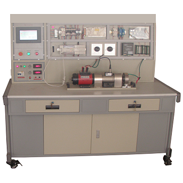


The motor performance comprehensive testing device integrates the control, operation, mechanical and electrical characteristics testing and teaching tr*ning of DC motors and AC motors. It is equipped with advanced detection and control means to conduct quantitative analysis and collection of the above various operating modes. Various parameters of motor operation. Students can collect data and display it through an embedded touch screen. This experimental bench is fully equipped with special power supply console, instruments, motors, guide r*ls, loads and special wires, as well as supporting software. It can better meet the teaching and research of various motor performance tests for DC motors, asynchronous motors, synchronous motors and other related majors in various colleges and universities.
The motor load adopts a new type of magnetic powder brake with high performance and long life, and the load adjustment is stable, reliable and convenient. It can perform steady-state testing or rapid instantaneous testing. A touch screen based on the W in CE (Chinese version) operating system and embedded with the Homebuilder embedded version configuration software is used as a human-machine interface. It serves as a data input, display monitoring and control terminal in the system. The terminal uses the RS-485/232 interface acquisition module for communication. The data acquisition module uploads the sensor detection values to the terminal for display or monitoring.
2. Technical performance
1. Input power supply: three-phase four-wire (or three-phase five-wire) ~ 380V ± 10% 50Hz
2. Working environment: temperature -10℃ ~ +40℃, relative humidity < 85% (25℃) altitude < 4000m
3. Safety protection: equipped with leakage voltage and leakage current protection devices, safety in line with national standards
4. Measurement parameters and accuracy:
AC and DC current: ±0.5%
AC and DC voltage: ±0.5%
Power: ±0.5%
speed and rotation Difference: ±0.1%
Torque: ±0.1%
Winding resistance: ±0.2%
2. Basic system equipment
1. Power console
(1) AC power supply
Three-phase four-wire (or three-phase five-wire) ~ 380V±10% 50Hz (10A) Overcurrent protection measures
Single phase 0~220V±10% 50Hz (10A) Overcurrent protection measures
The AC power output is equipped with over-current protection technology, which can automatically protect phase-to-phase and line-to-line overcurrents and direct short circuits. Equipped with a pointer AC voltmeter, which indicates the three-phase grid voltage through a switch.
(2) DC power supply
Provide a DC speed regulator and a potentiometer to adjust the output voltage.
The synchronous motor excitation power supply is adjustable from 0-24V.
2. Motor guide r*ls fix the motor unit.
3. Motor
(1) DQ09 DC motor (220V / 185W)
(Un=DC220V, IN=1.1A, PN=185W, n=1500RPM, insulation grade E)
(2) Single-phase capacitor starting asynchronous motor
(AC220V, speed 1400 RPM, power 90W, current 1.45A, starting capacitor 35uF, insulation class E)
(3) Three-phase asynchronous motor
(AC3800V/220V, connection Y/Δ, rotation speed 1420 RPM, power 100W, current 0.5A, insulation grade E)
(4) Three-phase synchronous motor
When used as a generator, PN (W) = 170W, UN (V) = 220 (Y), IN (A) = 0.45A, nN (r/min) = 1500, UfN (V) = 14V, IfN (A) =1.2A, insulation grade E.
(When used as a motor, PN (W) = 90W, UN (V) = 220 (Y), IN (A) = 0.35A, nN (r/min) = 1500, UfN (V) = 10V, IfN (A )=0.8A, insulation grade E.
4. Torque speed sensor
Dynamic torque sensor 20Nm,
5. Load: magnetic powder brake
A set of magnetic powder brake 20Nm, 0-1A steady current power supply, used to control the magnetic powder brake.
6. Microcomputer torque meter
Provide torque, speed, output power tester
7. Current, voltage and power acquisition module
EDA9033A three-phase comprehensive parameter detection module has single/three-phase voltage, current, active power, reactive power, power factor, frequency and other detection functions.
8. Related test software (HMIBuilder embedded version configuration software)
The configuration software running environment based on the touch screen realizes data collection and display to realize a series of control operations of the electric motive system.
9. Embedded human-machine interface device
7" high-brightness TFT LCD display, resolution 800×480, four-wire resistive touch screen, resolution 1024×1024.
WinCE (Chinese version) operating system, embedded HMIBuilder embedded version configuration software unlimited points. M*n frequency 400M, Memory 64M, storage device 128M electronic disk.
Working power supply DC24V
has two 2.0 USB interfaces, supports project backup and restore, supports external input interface devices, such as USB mouse and keyboard, etc.
It has two DB9 interfaces, COM1 is RS-232 interface. , COM2 has an RS-232 interface and RS-485 interface,
supports Modbus protocol communication, and the module address can be set manually.
10. Teaching software
1. Electrical safety and electric shock first *d simulation teaching software
The software uses a combination of two-dimensional and three-dimensional virtual images to teach students the safety and first *d methods of using electricity. The software includes single-phase electric shock, two-phase electric shock, step electric shock, low-voltage electric shock first *d, high-voltage electric shock first *d, artificial respiration first *d, Principles of hand-holding breathing rescue method, chest cardiac compression and other protective methods are expl*ned and taught. Principles of single-phase electric shock are divided into rep*ring live disconnection, rep*ring socket electric shock, and outdoor electric shock. The teaching of low-voltage electric shock and high-voltage electric shock m*nly expl*ns and demonstrates to students how to rescue people who are suffering from low-voltage electric shock or high-voltage electric shock. Artificial respiration rescue method, hand-holding breathing rescue method, and chest cardiac compression rescue method are demonstrated using 3D virtual simulation technology. After rendering and Polish it to make the model look like the real part and look realistic. Through practical tr*ning, students can be educated on the safe use of electricity in the tr*ning room, improve students' safety awareness, and enable students to learn some self-rescue methods, so that students can take cert*n safety measures to protect themselves when encountering danger, and become familiar with various Causes of electrical accidents and practical measures to deal with them to reduce the occurrence of electrical accidents.
2. M*ntenance of electricians , electronic motors and vocational qualification tr*ning assessment simulation software
This software is in apk format and can be used on PC or mobile. This software can set faults manually or automatically. This software can manually set fault points through the green box in the circuit diagram (you can set up to 39 fault points), you can also automatically set one random fault point, two random fault points, three random fault points, four random fault points, and five random fault points through the system. It has functions such as toolbox, component library, magnifying glass, circuit diagram, etc. You can choose a multimeter for testing through the toolbox, select appropriate components through the component library, and clearly understand each component and circuit through the magnifying glass. This software allows students to understand the working principle and circuit structure of the motor star-delta start control circuit through the setting of faults in the motor star-delta start control circuit and various investigations.
3. Virtual spectrum analyzer, logic analyzer, oscilloscope, and three-meter simulation software:
This software is in apk format and can be used on PC or mobile terminals. The functions of this software are: resistance measurement, AC voltage measurement (measuring transformer, if the multimeter burns out when measuring the transformer, black smoke will emit prompts and can reset the multimeter), determine the polarity of the transistor, measure the DC voltage (the light turns on when the ammeter is turned on), measure the DC current, and determine the quality of the capacitor. This software can drag the red and black pen tips at will. When the two pen tips are dragged and positioned on the measured object, a red circle will be displayed. If the positioning is not accurate, no red circle will be displayed, and when incorrect operations are performed (such as the wrong range selected, If the measured data is wrong, etc.), the meter pointer will not respond, prompting errors and re-measurement, etc. This multimeter can select AC voltage range, DC voltage range, resistance range, current range, resistance adjustment to 0, and can enlarge the display data. Clearly view the measured data size. Students can learn the correct use of multimeters through this software.
4. Microcontroller and plc programmable design and control virtual simulation software:
This software is developed based on unity3d and has built-in experimental steps, experimental instructions, circuit diagrams, component lists, connection lines, power on, circuit diagrams, scene reset, return and other buttons. After the connections and codes are correct, you can start/stop, The forward movement and reverse movement buttons operate the 3D machine tool model to move. In the connected line state, the 3D machine tool model can be enlarged/reduced and translated.
1. Relay control: Read the experiment instructions and enter the experiment. By reading the circuit diagram, select the relays, thermal relays, switches and other components in the component list and drag and drop them into the electrical cabinet. The limiters are placed in the three-dimensional On the machine tool model, you can choose to cover it, and some component names can be renamed. Then click the Connect Line button to connect terminals to terminals. After successfully connecting the machine tool circuit, choose to turn on the power and proceed. If the component or line An error box will pop up if there is a connection error, and the scene can be reset at any time.
2. PLC control: The experiment is the same as relay control, with the addition of PLC control function. After the connection is completed, enter the program writing interface through the PLC coding button, and write two programs, forward and reverse, with a total of 12 ladder diagram symbols. The writing is completed. Finally, select Submit for program verification. After the verification is successful, turn on the power for operation. Error boxes will pop up for component, line connection, and code errors, and the scene can be reset at any time.
3. Single-chip microcomputer control: The experiment is the same as relay control, with the addition of single-chip microcomputer control function. After the connection is completed, enter the programming interface through the C coding button, enter the correct C language code, and after successful submission and verification, turn on the power for operation, components, lines If there are connection or code errors, an error box will pop up, and the scene can be reset at any time.
3. Experiment content
1. DC motor experiment
(1) DC motor no-load characteristic test
(2) DC motor load test
(3) DC motor efficiency measurement
(4) DC motor characteristic curve measurement
(5) DC motor cold resistance and temperature Liter experiment and other experiments
(6) Measurement of speed, output torque, power, voltage and current of DC motor
2. Single-phase capacitor started asynchronous motor experiment
(1) Single-phase capacitor started asynchronous motor no-load characteristic test
(2) Single-phase capacitor started asynchronous motor stall test (3) Single-phase capacitor started asynchronous motor load characteristic test (4) Single-
phase capacitor started asynchronous motor
Phase capacitor started asynchronous motor efficiency measurement
(5) Single-phase capacitor started asynchronous motor characteristic curve measurement
(6) Single-phase capacitor started asynchronous motor cold resistance and temperature rise experiment
(7) Measurement of speed, output torque, power, voltage and current of single-phase capacitor-start asynchronous motor
3. Three-phase asynchronous motor experiment
(1) Three-phase asynchronous motor no-load characteristic test
(2) Three-phase asynchronous motor stall test
(3) Three-phase asynchronous motor load characteristic test
(4) Three-phase asynchronous motor efficiency measurement
(5) Three-phase asynchronous motor characteristic curve measurement
(6) Three-phase asynchronous motor cold resistance and temperature rise experiment
(7) Measurement of speed, output torque, power, voltage and current of three-phase asynchronous motor
4. Three-phase synchronous motor experiment
(1) Starting of three-phase synchronous motor
(2) No-load characteristic test of three-phase synchronous motor
(3) Three-phase synchronous motor load characteristic test
(4) Three-phase synchronous motor efficiency measurement
(5) Three-phase synchronous motor characteristic curve measurement
(6) Three-phase synchronous motor V-shaped curve measurement
(7) Three-phase synchronous motor cold resistance and temperature rise Experiments, etc.
(8) Measurement of rotation speed, output torque, power, voltage and current of three-phase synchronous motor.
Hot-selling products: Electrical experimental bench
 Wechat scan code follow us

24-hour hotline+86 18916464525

Phone18916464525
ADD:Factory 414, District A, No. 6, Chongnan Road, Songjiang Science and Technology Park, Shanghai ICP: Sitemap