Shanghai Daiyu Education Equipment Manufacturing Co., Ltd.
Language:


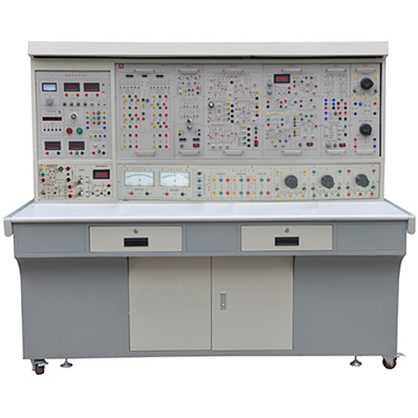


" Motor Power Electronics and Motion Control Experimental Device" integrates the current "Electrical Machinery", "Motor and Drag", "Control Micromotors", "Motor Control", "Factory Electrical Control" and "Power Electronics Technology" in China's higher education institutions. Requirements for the experimental syllabus of courses such as "Electric Drag Automatic Control System". It is especially suitable for the upgrading and transformation of existing motor and electrical technology experimental equipment in colleges and universities. It also provides ideal experimental equipment for new or expanded laboratories and rapid opening of experimental courses in secondary vocational schools, vocational and technical colleges, etc., and provides ideal experimental equipment for teachers or It provides good experimental conditions for graduate students to develop new experiments or conduct scientific research.
2. Characteristics
1. Strong comprehensiveness: This device integrates all experimental projects of electrical and electrical courses in various domestic colleges and universities.
2. Strong adaptability. It can satisfy the experimental teaching of corresponding courses in various schools. The depth and breadth of experiments can be flexibly adjusted according to needs. Popularization and improvement can be organically combined according to the teaching process. The device adopts a component structure and is easy to replace. If you need to expand functions or develop new experiments, you only need to add components and it will never be eliminated.
3. Strong complete set: From instruments and meters, special power supply, motors and other experimental components to special wires for experimental connection, it is fully equipped. The performance and specifications of the supporting components are closely combined with the needs of the experiment.
4. Strong intuitiveness. Each experimental pendant adopts a separated structure, with component panels and clear diagrams. Each pendant has clear tasks and is easy to operate and m*nt*n.
5. The highly scientific device occupies a small area, saving experimental space and reducing infrastructure investment; the supporting small motors are specially designed to simulate the characteristics and parameters of small and medium-sized motors; small motors consume less power and save energy; experimental noise Small, neat and beautiful, improving the experimental environment; the electrical control experiment is rich in content and reasonably designed. In addition to deepening theoretical knowledge, it also lays a good foundation for students to enter the society; the measuring instruments adopt pointer type (with over-range alarm, etc.), digital type , intelligence and human-machine dialogue are combined, and the configuration is closely combined with the needs of teaching experiments to modernize the device measurement methods; it is equipped with a timer and alarm recorder to provide a unified standard for the assessment of students' experimental skills.
6. The control panel has strong openness and power supply isolation (floating design), and is equipped with internal and external voltage-type leakage protection devices and current-type leakage protection devices to ensure the safety of the operator; each power output has monitoring and short-circuit protection, etc. Functional and easy to use; each measuring instrument has a protection function. The entire device is carefully designed, guaranteed by reliable component quality and reliable technology, and has excellent product performance. All of these create conditions for open experiments and are conducive to improving students' ability to analyze and solve problems.
3. Technical performance
1. Input power: three-phase four-wire (or three-phase five-wire) ~380V±10% 50Hz
2. Working environment: temperature -10℃~+40℃, relative humidity <85% (25℃), altitude <4000m
3. Device capacity: <1.5KVA
4. Weight: 480Kg
5. Overall dimensions: 187×700×160cm3
4. Experimental projects
(1) Power electronics technology experiment
1. Power electronics technology experimental project (thyristor circuit)
(1) Unijunction transistor trigger circuit
(2) Sine wave synchronous phase-shift trigger circuit experiment
(3) Sawtooth wave synchronous phase-shift trigger circuit experiment
(4) Siemens TCA785 integrated trigger circuit experiment
(5) Single-phase half-wave controllable rectifier circuit experiment
(6) Single-phase bridge semi-controlled rectifier circuit experiment
(7) Single-phase bridge fully controlled rectifier and active inverter circuit experiment
(8) Three-phase half-wave controllable rectifier circuit and active inverter circuit experiment
(9) Three-phase bridge semi-controlled rectifier circuit experiment
(10) Three-phase bridge type fully controlled rectifier and active inverter circuit experiment
(11) Single-phase AC voltage regulating circuit experiment
(12) Three-phase AC voltage regulating circuit experiment
2. Power electronics technology experimental project (power electronic device characteristics and drive protection)
(13) Unidirectional thyristor (SCR) characteristics experiment
(14) Power field effect transistor (MOSFET) characteristics experiment
(15) Power transistor (GTR) characteristics experiment
(16) Insulated Bipolar Transistor (IGBT) Characteristics Experiment
(17) Power field effect transistor (MOSFET) driving and protection circuit experiment
(18) Insulated bipolar transistor (IGBT) driving and protection circuit experiment
3. Power electronics technology experimental project (typical circuit experiment of power electronic devices)
(1) Single-phase sine wave pulse width modulation (SPWM) inverter circuit experiment
(2) Performance study of DC chopper circuit
(Buck chopper circuit, boost chopper circuit, buck-boost chopper circuit, Cuk chopper circuit, Sepic chopper circuit, Zeta chopper circuit)
(3) Full-bridge DC/DC conversion circuit (IGBT)
4. Electric drag automatic control experiment
(1) Debugging of the m*n units of the thyristor DC speed control system (SCR)
(2) Open-loop thyristor DC speed regulation system experiment
(3) Single closed loop (voltage single closed loop, speed single closed loop, current single closed loop) irreversible DC speed control system experiment (SCR)
(4) Experiment on current-speed double closed-loop control thyristor irreversible DC speed regulation system
(5 Current speed double closed-loop control reversible DC pulse width speed regulation system (H bridge, IGBT)
(6) Three-phase asynchronous motor voltage and speed regulation system experiment
(2) Basic experiments on motor and drag
1. Transformer experiment
(1) Single-phase transformer
(2) Three-phase transformer
(3) Connection group and asymmetric short circuit of three-phase transformer
(4) Three-phase three-winding transformer
(5) Parallel operation of single-phase transformers
(6) Parallel operation of three-phase transformers
2. DC motor experiment
(1) DC motor understanding experiment
(2) DC generator
(3) Starting and speed regulation experiments of DC shunt motors
3. Asynchronous motor experiment
(1) Operating characteristics of three-phase squirrel cage asynchronous motor
(2) Starting and speed regulation of three-phase asynchronous motors
5. Determination of mechanical characteristics of electric motors
(1) Mechanical characteristics of DC separately excited motors under various operating conditions
(2) Mechanical characteristics of three-phase asynchronous motors under various operating conditions
(3) Surveying and mapping of three-phase asynchronous motor MS curve
5. Device configuration
1. DQ01 power control panel (iron plastic spray structure, aluminum panel)
(1) AC power supply
Provides three-phase 0~450V adjustable AC power supply, and at the same time can obt*n single-phase 0~250V adjustable power supply (equipped with a three-phase linkage auto-coupling voltage regulator (specification 1.5KVA, 0~450V), overcoming the problem of three single-phase There are many disadvantages to using a ch*n structure or a gear structure for phase voltage regulators). The output of the adjustable AC power supply is equipped with over-current protection technology. Inter-phase, inter-line over-current and direct short circuit can be automatically protected, overcoming the trouble caused by replacing fuses. Equipped with three pointer AC voltmeters, which indicate the three-phase grid voltage and the three-phase voltage regulation voltage through the switch.
Provide one three-phase synchronous transformer with voltage 380V//3*15V.
(2) Two circuits of high-voltage DC power supply
Provides one set of 220V (0.5A) excitation power supply and 0~250V (3A) continuously adjustable regulated armature power supply (with internal overvoltage and overcurrent protection functions), and is equipped with a DC digital display voltmeter and a switch.
(3) Personal safety protection system
It is equipped with a set of three-phase isolation transformers (the three-phase power supply passes through the key switch and contactor, then to the isolation transformer, and then is output through the three-phase voltage regulator) to isolate the output from the power grid and play a cert*n protective role in personal safety; There is a current type leakage protector. If there is leakage on the control panel and the leakage current exceeds a cert*n value, the power supply will be cut off. The strong current connecting wires and sockets adopt a fully enclosed structure, which is safe, reliable and prevents electric shock. It is equipped with a voltage type leakage protector. If there is leakage during the experiment, an alarm function will be issued and the power will be cut off. The strong current connecting wires and sockets adopt a fully enclosed structure, which is safe, reliable and prevents electric shock.
(4) There are two round steel pipes in the large groove on the front of the control panel, which can hang instruments and experimental components. There are multiple small round single-phase three-core 220V power sockets at the bottom of the groove for power supply to instruments and other components. There are three-pole 220V power sockets and three-phase four-pole 380V power sockets on both sides of the control panel. There is a 220V, 40W fluorescent lamp for experimental bench
lighting. (5) Teaching software
1. Electrical safety and electric shock first *d simulation teaching software
The software uses a combination of two-dimensional and three-dimensional virtual images to teach students the safety and first *d methods of using electricity. The software includes single-phase electric shock, two-phase electric shock, step electric shock, low-voltage electric shock first *d, high-voltage electric shock first *d, artificial respiration first *d, Principles of hand-holding breathing rescue method, chest cardiac compression and other protective methods are expl*ned and taught. Principles of single-phase electric shock are divided into rep*ring live disconnection, rep*ring socket electric shock, and outdoor electric shock. The teaching of low-voltage electric shock and high-voltage electric shock m*nly expl*ns and demonstrates to students how to rescue people who are suffering from low-voltage electric shock or high-voltage electric shock. Artificial respiration rescue method, hand-holding breathing rescue method, and chest cardiac compression rescue method are demonstrated using 3D virtual simulation technology. After rendering and Polish it to make the model look like the real part and look realistic. Through practical tr*ning, students can be educated on the safe use of electricity in the tr*ning room, improve students' safety awareness, and enable students to learn some self-rescue methods, so that students can take cert*n safety measures to protect themselves when encountering danger, and become familiar with various Causes of electrical accidents and practical measures to deal with them to reduce the occurrence of electrical accidents.
2. M*ntenance of electricians , electronic motors and vocational qualification tr*ning assessment simulation software
This software is in apk format and can be used on PC or mobile. This software can set faults manually or automatically. This software can manually set fault points through the green box in the circuit diagram (you can set up to 39 fault points), you can also automatically set one random fault point, two random fault points, three random fault points, four random fault points, and five random fault points through the system. It has functions such as toolbox, component library, magnifying glass, circuit diagram, etc. You can choose a multimeter for testing through the toolbox, select appropriate components through the component library, and clearly understand each component and circuit through the magnifying glass. This software allows students to understand the working principle and circuit structure of the motor star-delta start control circuit through the setting of faults in the motor star-delta start control circuit and various investigations.
3. Virtual spectrum analyzer, logic analyzer, oscilloscope, and three-meter simulation software:
This software is in apk format and can be used on PC or mobile terminals. The functions of this software are: resistance measurement, AC voltage measurement (measuring transformer, if the multimeter burns out when measuring the transformer, black smoke will emit prompts and can reset the multimeter), determine the polarity of the transistor, measure the DC voltage (the light turns on when the ammeter is turned on), measure the DC current, and determine the quality of the capacitor. This software can drag the red and black pen tips at will. When the two pen tips are dragged and positioned on the measured object, a red circle will be displayed. If the positioning is not accurate, no red circle will be displayed, and when incorrect operations are performed (such as the wrong range selected, If the measured data is wrong, etc.), the meter pointer will not respond, prompting errors and re-measurement, etc. This multimeter can select AC voltage range, DC voltage range, resistance range, current range, resistance adjustment to 0, and can enlarge the display data. Clearly view the measured data size. Students can learn the correct use of multimeters through this software.
4. Microcontroller and plc programmable design and control virtual simulation software:
This software is developed based on unity3d and has built-in experimental steps, experimental instructions, circuit diagrams, component lists, connection lines, power on, circuit diagrams, scene reset, return and other buttons. After the connections and codes are correct, you can start/stop, The forward movement and reverse movement buttons operate the 3D machine tool model to move. In the connected line state, the 3D machine tool model can be enlarged/reduced and translated.
1. Relay control: Read the experiment instructions and enter the experiment. By reading the circuit diagram, select the relays, thermal relays, switches and other components in the component list and drag and drop them into the electrical cabinet. The limiters are placed in the three-dimensional On the machine tool model, you can choose to cover it, and some component names can be renamed. Then click the Connect Line button to connect terminals to terminals. After successfully connecting the machine tool circuit, choose to turn on the power and proceed. If the component or line An error box will pop up if there is a connection error, and the scene can be reset at any time.
2. PLC control: The experiment is the same as relay control, with the addition of PLC control function. After the connection is completed, enter the program writing interface through the PLC coding button, and write two programs, forward and reverse, with a total of 12 ladder diagram symbols. The writing is completed. Finally, select Submit for program verification. After the verification is successful, turn on the power for operation. Error boxes will pop up for component, line connection, and code errors, and the scene can be reset at any time.
3. Single-chip microcomputer control: The experiment is the same as relay control, with the addition of single-chip microcomputer control function. After the connection is completed, enter the programming interface through the C coding button, enter the correct C language code, and after successful submission and verification, turn on the power for operation, components, lines If there are connection or code errors, an error box will pop up, and the scene can be reset at any time.
2. DQ02 experimental table
The experimental table is made of iron with a double-layer matt dense spray-p*nted structure. The tabletop is made of fireproof, waterproof and wear-resistant high-density board. It has a solid structure and is shaped like a rectangular closed structure. It has a beautiful and elegant appearance; it is equipped with two large drawers and cabinet doors. , used to place tools, store pendants and information, etc. The desktop is used to install the power control panel and provide a spacious and comfortable work surface. The experimental table is also equipped with four universal wheels and four fixed adjustment mechanisms, which are easy to move and fix, and are conducive to the layout of the laboratory.
3. DQ03-1 motor guide r*l, speed measurement system and intelligent digital display tachometer
Including tachometer generator and guide r*ls for fixing the motor, etc. The guide r*l has good flatness, no stress deformation, fine processing, good concentricity, and good interchangeability. It can ensure a good connection between motors and motors, motors and dynamometers. The motor has low operating noise, typical experimental parameters, and can be compared. So as to meet the experimental requirements.
4. DQ05 three-phase transformer (composed of three identical single-phase transformers, primary side 220V/0.35A, secondary side 55V/1.4A)
5. DQ07 DC compound-excited generator (Un=DC200V, IN=0.5A, PN=100W, n=1600RPM, insulation grade E)
6. DQ09 DC parallel (separately) excited motor (Un=DC220V, IN=1.1A, PN=185W, n=1500RPM, insulation grade E)
7. DQ10 three-phase squirrel cage asynchronous motor (AC3800V/220V, connection Y/Δ, speed 1420 RPM, power 100W, current 0.5A, insulation grade E)
8. DQ11 three-phase wire-wound asynchronous motor (AC220V, connection Y, speed 1380 RPM, power 120W, current 0.6A, insulation grade E)
9. GDQ12 wire-wound asynchronous motor starting and speed regulating resistor box
Provides a set of 0, 2, 5 and 15 three-phase wound asynchronous motor rotor starting and speed regulating resistors.
10. DQ19 calibrated DC dynamometer (220V, 2.2A, 355W, 1500r/min)
It can be used as both a motor and a dynamometer. When used as a motor, it can be used as the prime mover of a generator or to drag the motor to complete the four-quadrant test. When used as a dynamometer, due to the special design of the motor, the capacity is 2 to 3 times that of the motor under test, and calibrated by precision instruments, it can well complete the test of the load output torque of the motor under test.
11. DQ22 DC digital voltage, milliampere, and ammeter (three pieces)
A DC digital display voltmeter is designed using ICL's high-performance AD converter and high-speed MPU unit. It realizes human-machine dialogue function control mode through key control and digital display window. It has automatic and manual ranges, and the measuring range is 0-300V. Manual ranges are: 2V, 20V, 300V. The measurement accuracy is 0.5 level. It has data storage and query functions. It has the functions of over-range alarm, indication and cutting off the m*n power supply.
A DC digital display milliamp meter is designed using ICL's high-performance AD converter and high-speed MPU unit. It realizes human-machine dialogue function control mode through key control and digital display window. With automatic and manual range, measuring range: 0-2000mA. Manual ranges are: 20mA, 200mA, 2000mA. The measurement accuracy is 0.5 level. It has data storage and query functions. It has the functions of over-range alarm, indication and cutting off the m*n power supply.
A DC digital display ammeter with a measuring range of 0 to 5A, a three-and-a-half-digit display, and an accuracy of 0.5. It has the functions of over-range alarm, indication, and cutting off the m*n power supply.
12. DQ25 single three-phase intelligent power and power factor meter
Designed by 24-bit dedicated DSP, 16-bit high-precision AD converter and high-speed MPU unit, it realizes human-machine dialogue function control mode through key control and digital display window. The software adopts RTOS design ideas and is equipped with PC monitoring software to enhance analysis capabilities. It can measure two single-phase powers P1 and P2 at the same time. The three-phase power is equal to the sum of the two-channel powers (the two-meter method measures the total three-phase power). The power measurement accuracy is level 1.0, the power factor measurement range is 0.3-1.0, the voltage and current range is 450V and 5A, and it can automatically determine the load properties (inductive display "L", capacitive display "C", pure resistance does not display), and can Store measurement data for review at any time.
13. DQ26 three-phase adjustable resistor (three sets of 90Ω×2/1.3A ceramic plate resistors)
14. DQ27 three-phase adjustable resistor (three sets of 900Ω×2/0.41A ceramic plate resistors)
15. DQ29 adjustable resistor and capacitor
Provides one set of 90Ω×2/1.3A and 900Ω×2/0.41A ceramic disk resistors, and one each of 35μF/450V and 4μF/450V power capacitors.
16. DQ31 waveform test and switch board
It consists of a transformer waveform test part, two three-pole double-throw switches, and one double-pole double-throw switch.
17. DQ44 digital/analog AC ammeter
It consists of three digital AC ammeters and one pointer precision AC current meter. Measuring range 0~5A, automatic range judgment and automatic switching, accuracy level 0.5, four-digit digital display. A pointer type precision AC ammeter, using a meter head with a mirror and double scale marks (red and black) (read the corresponding scale marks for different ranges). The measuring range is 0~5A, divided into four categories: 0.3A, 1A, 3A and 5A. level, accuracy level 1.0, direct key switch, equipped with over-range indication, alarm and other functions.
18. DQ45 digital/analog AC voltmeter
It consists of three digital AC voltmeters and one pointer precision AC current meter. Measuring range: 0~450V, automatic range judgment and automatic switching, accuracy level 0.5, four-digit digital display. A pointer-type precision AC voltmeter, using a meter head with a mirror and double scale lines (red and black) (read the corresponding scale lines for different ranges), with a measuring range of 0 to 500V, divided into 10V, 30V, 100V, and 300V. 500V five-speed, accuracy level 1.0, direct key switch, equipped with over-range indication, alarm and other functions.
19. DK03 thyristor m*n circuit
Provides 6 5A/1000V thyristors and 6 5A/1000V diodes. Each thyristor is equipped with a protection device. The thyristor can be triggered by an external signal (a trigger pulse input interface is left), which can better complete design experiments. ; Equipped with a precision pointer-type DC voltmeter with a mirror of ±300V, a DC ammeter with a mirror accuracy of ±2A with an accuracy of 1.0, and a set of smoothing reactors with an accuracy of 1.0.
20. DK04 three-phase thyristor trigger circuit
Three-phase thyristor trigger circuit, power amplifier circuit, etc. are provided for use with "DK03" and have waveform test holes.
21. DK05 single-phase thyristor trigger circuit
A total of five trigger circuits are provided: single-junction transistor trigger circuit, sine wave synchronous phase-shift trigger circuit, sawtooth wave synchronous phase-shift trigger circuit, single-phase AC voltage regulation trigger circuit and Siemens TCA785 trigger circuit.
22. DK06 motor speed control experiment (Ⅰ)
The following modules are provided: given (with digital display), regulator I, speed conversion (FBS), regulator II, signal inverter (AR), and current conversion (FBC). The proportional g*ns of regulator I and regulator II are adjusted by potentiometers.
23. DK07 DC chopper experiment
Designed based on the relevant DC chopper content in "Power Electronics Technology" (Fourth Edition) edited by Professor Wang Zhaoan and Professor Huang Jun of Xi'an Jiaotong University; provides the components required to form a DC chopper circuit and adopts dedicated PWM control Integrated circuit SG3525. Can complete the buck chopper circuit (Buck Chopper), boost chopper circuit (Boost Chopper), boost-buck chopper circuit (Boost-Buck Chopper), Cuk chopper circuit, Sepic chopper circuit, and Zeta chopper in the textbook Six typical experiments on circuits.
24. DK08 given and experimental devices
Provides a given (±15V adjustable voltage output), varistor (as an overvoltage protection component, internally connected in a delta connection), diode, BCR, etc.
25. DK10 adjustable resistor, capacitor
Provide three sets of adjustable capacitors with a voltage of AC100V, with an adjustment range of 0.1~11.37uF, and two sets of decimal adjustable resistors of 0~999KΩ.
26. DK12 transformer experiment
Provide a three-phase core transformer (the transformer has 2 sets of secondary windings, the voltage of the primary and secondary windings is 127V/63.6V/31.8V), used for asynchronous motor cascade speed regulation experiments and three-phase bridge, single Phase bridge active inverter circuit experiment; there are also modules such as three-phase uncontrolled rectifier circuit.
27. DK13 power device drive circuit experiment (1)
The m*n purpose is to provide driving and protection circuits for completing experiments on new device characteristics, so that students can understand the driving characteristics of new power electronic devices. It m*nly includes power supply, drive circuit and PWM waveform generator.
(1) Power supply: Provide power for the drive circuit, including ±5V, +20V, ±15V DC power supply.
(2) Drive circuit: including drive circuits for MOSFET and IGBT. The IGBT drive circuit uses a dedicated chip EXB841.
(3) PWM waveform generator: The PWM waveform generator with SG3525 as the core m*nly provides PWM drive waveforms for new device drive circuits; the frequency can be adjusted through the frequency adjustment knob; the duty cycle of the PWM wave can be adjusted through the duty cycle potentiometer. Ratio frequency adjustment range is 4KHz~10KHz.
28. DK14 single-phase AC and DC frequency conversion principle
Developed based on the relevant content of "Power Electronics Technology" (Fourth Edition) edited by Wang Zhaoan and Huang Jun, a national key textbook for general higher education during the "Ninth Five-Year Plan", it is used to demonstrate the principle of AC, DC and AC frequency conversion, m*nly to allow students to understand SPWM sine waves The formation method of pulse width modulation signal, and understand the characteristics and use of IGBT tube-specific integrated driver chip. Be able to complete the following experimental projects: 1. The process of SPWM wave formation; 2. The working conditions and waveforms of AC-AC frequency conversion circuits under different loads, and study the impact of operating frequency on the circuit operating waveforms; 3. The design of special integrated driver chips for IGBT tubes Working characteristics.
29. DK17 double closed-loop H-bridge DC/DC conversion DC speed control system
The m*n circuit and control circuit of the DC/DC conversion circuit experiment are provided. The LEM sensor is used as current detection, the power electronic device is IGBT, the control circuit uses PWM control integrated circuit SG3525, and the required observation holes are also provided on the hanging box panel. The experimental projects that can be completed include:
(1) Full-bridge DC/DC conversion circuit experiment;
(2) Double closed-loop reversible DC pulse width speed regulation experiment.
30. Tr*ning cables and accessories
The structure of the pistol plug connection cable (there is no possibility of electric shock) is made of oxygen-free copper and made into h*r-thin multi-strand wires to achieve the purpose of ultra-softness. It is covered with a nitrile polyvinyl chloride insulation layer, which is soft and durable. It has the advantages of high pressure, high strength, anti-hardening, and good toughness. The plug is made of solid copper and beryllium light copper shrapnel, which has excellent contact.
7. Equipment configuration list
|
Serial number |
serial number |
Name |
quantity |
Remark |
|
1 |
DQ01 |
Power control panel |
1 set |
|
|
2 |
DQ02 |
Experiment table |
1 piece |
|
|
3 |
DQ03-1 |
Motor guide r*l, speed measurement system and intelligent digital display tachometer |
1 item |
|
|
4 |
DQ05 |
Three-phase transformer |
1 item |
|
|
5 |
DQ07 |
DC compound generator |
1 set |
|
|
6 |
DQ09 |
DC shunt motor |
1 set |
|
|
7 |
DQ10 |
Three-phase squirrel cage asynchronous motor |
1 set |
|
|
8 |
DQ11 |
Three-phase wire-wound asynchronous motor |
1 set |
|
|
9 |
GDQ12 |
Wirewound asynchronous motor starting and speed regulating resistor box |
1 item |
|
|
10 |
DQ19 |
Calibrating DC Dynamometer |
1 set |
|
|
11 |
DQ22 |
DC digital voltage, milliampere, and ammeter (three meters) (Note: According to the experimental requirements, each set requires 2 pieces) |
2 pieces |
|
|
12 |
DQ44 |
Digital/Analog AC Ammeter |
1 item |
|
|
13 |
DQ45 |
Digital/Analog AC Voltmeter |
1 item |
|
|
14 |
DQ25 |
Single/three-phase intelligent power and power factor meter |
1 item |
|
|
15 |
DQ26 |
Three-phase adjustable resistor (90Ω*2/1.3A per group) |
1 item |
|
|
16 |
DQ27 |
Three-phase adjustable resistor (900Ω*2/0.41A per group) |
1 item |
|
|
17 |
DQ29 |
Adjustable resistors and capacitors |
1 item |
|
|
18 |
DQ31 |
Waveform test and switch board |
1 item |
|
|
19 |
DK03 |
Thyristor m*n circuit |
1 item |
|
|
20 |
DK04 |
Three-phase thyristor trigger circuit |
1 item |
|
|
twenty one |
DK05 |
Single phase thyristor trigger circuit |
1 item |
|
|
twenty two |
DK06 |
Motor speed control experiment (Ⅰ) |
1 item |
|
|
twenty three |
DK07 |
DC chopper circuit |
1 item |
|
|
twenty four |
DK08 |
Given and experimental devices |
1 item |
|
|
25 |
DK10 |
Adjustable resistors, capacitors |
1 item |
|
|
26 |
DK12 |
Transformer experiment |
1 item |
|
|
27 |
DK13 |
Power device drive circuit experiment box |
1 item |
|
|
28 |
DK14 |
Single-phase AC and DC frequency conversion principle |
1 item |
|
|
29 |
DK17 |
Double closed-loop H-bridge DC/DC conversion DC speed regulation system |
1 item |
|
|
30 |
Highly reliable sheath structure pistol plug experimental connection cable and accessories |
1 set |
" Motor Power Electronics and Motion Control Experimental Device" integrates the current "Electrical Machinery", "Motor and Drag", "Control Micromotors", "Motor Control", "Factory Electrical Control" and "Power Electronics Technology" in China's higher education institutions. Requirements for the experimental syllabus of courses such as "Electric Drag Automatic Control System". It is especially suitable for the upgrading and transformation of existing motor and electrical technology experimental equipment in colleges and universities. It also provides ideal experimental equipment for new or expanded laboratories and rapid opening of experimental courses in secondary vocational schools, vocational and technical colleges, etc., and provides ideal experimental equipment for teachers or It provides good experimental conditions for graduate students to develop new experiments or conduct scientific research.
2. Characteristics
1. Strong comprehensiveness: This device integrates all experimental projects of electrical and electrical courses in various domestic colleges and universities.
2. Strong adaptability. It can satisfy the experimental teaching of corresponding courses in various schools. The depth and breadth of experiments can be flexibly adjusted according to needs. Popularization and improvement can be organically combined according to the teaching process. The device adopts a component structure and is easy to replace. If you need to expand functions or develop new experiments, you only need to add components and it will never be eliminated.
3. Strong complete set: From instruments and meters, special power supply, motors and other experimental components to special wires for experimental connection, it is fully equipped. The performance and specifications of the supporting components are closely combined with the needs of the experiment.
4. Strong intuitiveness. Each experimental pendant adopts a separated structure, with component panels and clear diagrams. Each pendant has clear tasks and is easy to operate and m*nt*n.
5. The highly scientific device occupies a small area, saving experimental space and reducing infrastructure investment; the supporting small motors are specially designed to simulate the characteristics and parameters of small and medium-sized motors; small motors consume less power and save energy; experimental noise Small, neat and beautiful, improving the experimental environment; the electrical control experiment is rich in content and reasonably designed. In addition to deepening theoretical knowledge, it also lays a good foundation for students to enter the society; the measuring instruments adopt pointer type (with over-range alarm, etc.), digital type , intelligence and human-machine dialogue are combined, and the configuration is closely combined with the needs of teaching experiments to modernize the device measurement methods; it is equipped with a timer and alarm recorder to provide a unified standard for the assessment of students' experimental skills.
6. The control panel has strong openness and power supply isolation (floating design), and is equipped with internal and external voltage-type leakage protection devices and current-type leakage protection devices to ensure the safety of the operator; each power output has monitoring and short-circuit protection, etc. Functional and easy to use; each measuring instrument has a protection function. The entire device is carefully designed, guaranteed by reliable component quality and reliable technology, and has excellent product performance. All of these create conditions for open experiments and are conducive to improving students' ability to analyze and solve problems.
3. Technical performance
1. Input power: three-phase four-wire (or three-phase five-wire) ~380V±10% 50Hz
2. Working environment: temperature -10℃~+40℃, relative humidity <85% (25℃), altitude <4000m
3. Device capacity: <1.5KVA
4. Weight: 480Kg
5. Overall dimensions: 187×700×160cm3
4. Experimental projects
(1) Power electronics technology experiment
1. Power electronics technology experimental project (thyristor circuit)
(1) Unijunction transistor trigger circuit
(2) Sine wave synchronous phase-shift trigger circuit experiment
(3) Sawtooth wave synchronous phase-shift trigger circuit experiment
(4) Siemens TCA785 integrated trigger circuit experiment
(5) Single-phase half-wave controllable rectifier circuit experiment
(6) Single-phase bridge semi-controlled rectifier circuit experiment
(7) Single-phase bridge fully controlled rectifier and active inverter circuit experiment
(8) Three-phase half-wave controllable rectifier circuit and active inverter circuit experiment
(9) Three-phase bridge semi-controlled rectifier circuit experiment
(10) Three-phase bridge type fully controlled rectifier and active inverter circuit experiment
(11) Single-phase AC voltage regulating circuit experiment
(12) Three-phase AC voltage regulating circuit experiment
2. Power electronics technology experimental project (power electronic device characteristics and drive protection)
(13) Unidirectional thyristor (SCR) characteristics experiment
(14) Power field effect transistor (MOSFET) characteristics experiment
(15) Power transistor (GTR) characteristics experiment
(16) Insulated Bipolar Transistor (IGBT) Characteristics Experiment
(17) Power field effect transistor (MOSFET) driving and protection circuit experiment
(18) Insulated bipolar transistor (IGBT) driving and protection circuit experiment
3. Power electronics technology experimental project (typical circuit experiment of power electronic devices)
(1) Single-phase sine wave pulse width modulation (SPWM) inverter circuit experiment
(2) Performance study of DC chopper circuit
(Buck chopper circuit, boost chopper circuit, buck-boost chopper circuit, Cuk chopper circuit, Sepic chopper circuit, Zeta chopper circuit)
(3) Full-bridge DC/DC conversion circuit (IGBT)
4. Electric drag automatic control experiment
(1) Debugging of the m*n units of the thyristor DC speed control system (SCR)
(2) Open-loop thyristor DC speed regulation system experiment
(3) Single closed loop (voltage single closed loop, speed single closed loop, current single closed loop) irreversible DC speed control system experiment (SCR)
(4) Experiment on current-speed double closed-loop control thyristor irreversible DC speed regulation system
(5 Current speed double closed-loop control reversible DC pulse width speed regulation system (H bridge, IGBT)
(6) Three-phase asynchronous motor voltage and speed regulation system experiment
(2) Basic experiments on motor and drag
1. Transformer experiment
(1) Single-phase transformer
(2) Three-phase transformer
(3) Connection group and asymmetric short circuit of three-phase transformer
(4) Three-phase three-winding transformer
(5) Parallel operation of single-phase transformers
(6) Parallel operation of three-phase transformers
2. DC motor experiment
(1) DC motor understanding experiment
(2) DC generator
(3) Starting and speed regulation experiments of DC shunt motors
3. Asynchronous motor experiment
(1) Operating characteristics of three-phase squirrel cage asynchronous motor
(2) Starting and speed regulation of three-phase asynchronous motors
5. Determination of mechanical characteristics of electric motors
(1) Mechanical characteristics of DC separately excited motors under various operating conditions
(2) Mechanical characteristics of three-phase asynchronous motors under various operating conditions
(3) Surveying and mapping of three-phase asynchronous motor MS curve
5. Device configuration
1. DQ01 power control panel (iron plastic spray structure, aluminum panel)
(1) AC power supply
Provides three-phase 0~450V adjustable AC power supply, and at the same time can obt*n single-phase 0~250V adjustable power supply (equipped with a three-phase linkage auto-coupling voltage regulator (specification 1.5KVA, 0~450V), overcoming the problem of three single-phase There are many disadvantages to using a ch*n structure or a gear structure for phase voltage regulators). The output of the adjustable AC power supply is equipped with over-current protection technology. Inter-phase, inter-line over-current and direct short circuit can be automatically protected, overcoming the trouble caused by replacing fuses. Equipped with three pointer AC voltmeters, which indicate the three-phase grid voltage and the three-phase voltage regulation voltage through the switch.
Provide one three-phase synchronous transformer with voltage 380V//3*15V.
(2) Two circuits of high-voltage DC power supply
Provides one set of 220V (0.5A) excitation power supply and 0~250V (3A) continuously adjustable regulated armature power supply (with internal overvoltage and overcurrent protection functions), and is equipped with a DC digital display voltmeter and a switch.
(3) Personal safety protection system
It is equipped with a set of three-phase isolation transformers (the three-phase power supply passes through the key switch and contactor, then to the isolation transformer, and then is output through the three-phase voltage regulator) to isolate the output from the power grid and play a cert*n protective role in personal safety; There is a current type leakage protector. If there is leakage on the control panel and the leakage current exceeds a cert*n value, the power supply will be cut off. The strong current connecting wires and sockets adopt a fully enclosed structure, which is safe, reliable and prevents electric shock. It is equipped with a voltage type leakage protector. If there is leakage during the experiment, an alarm function will be issued and the power will be cut off. The strong current connecting wires and sockets adopt a fully enclosed structure, which is safe, reliable and prevents electric shock.
(4) There are two round steel pipes in the large groove on the front of the control panel, which can hang instruments and experimental components. There are multiple small round single-phase three-core 220V power sockets at the bottom of the groove for power supply to instruments and other components. There are three-pole 220V power sockets and three-phase four-pole 380V power sockets on both sides of the control panel. There is a 220V, 40W fluorescent lamp for experimental bench
lighting. (5) Teaching software
1. Electrical safety and electric shock first *d simulation teaching software
The software uses a combination of two-dimensional and three-dimensional virtual images to teach students the safety and first *d methods of using electricity. The software includes single-phase electric shock, two-phase electric shock, step electric shock, low-voltage electric shock first *d, high-voltage electric shock first *d, artificial respiration first *d, Principles of hand-holding breathing rescue method, chest cardiac compression and other protective methods are expl*ned and taught. Principles of single-phase electric shock are divided into rep*ring live disconnection, rep*ring socket electric shock, and outdoor electric shock. The teaching of low-voltage electric shock and high-voltage electric shock m*nly expl*ns and demonstrates to students how to rescue people who are suffering from low-voltage electric shock or high-voltage electric shock. Artificial respiration rescue method, hand-holding breathing rescue method, and chest cardiac compression rescue method are demonstrated using 3D virtual simulation technology. After rendering and Polish it to make the model look like the real part and look realistic. Through practical tr*ning, students can be educated on the safe use of electricity in the tr*ning room, improve students' safety awareness, and enable students to learn some self-rescue methods, so that students can take cert*n safety measures to protect themselves when encountering danger, and become familiar with various Causes of electrical accidents and practical measures to deal with them to reduce the occurrence of electrical accidents.
2. M*ntenance of electricians , electronic motors and vocational qualification tr*ning assessment simulation software
This software is in apk format and can be used on PC or mobile. This software can set faults manually or automatically. This software can manually set fault points through the green box in the circuit diagram (you can set up to 39 fault points), you can also automatically set one random fault point, two random fault points, three random fault points, four random fault points, and five random fault points through the system. It has functions such as toolbox, component library, magnifying glass, circuit diagram, etc. You can choose a multimeter for testing through the toolbox, select appropriate components through the component library, and clearly understand each component and circuit through the magnifying glass. This software allows students to understand the working principle and circuit structure of the motor star-delta start control circuit through the setting of faults in the motor star-delta start control circuit and various investigations.
3. Virtual spectrum analyzer, logic analyzer, oscilloscope, and three-meter simulation software:
This software is in apk format and can be used on PC or mobile terminals. The functions of this software are: resistance measurement, AC voltage measurement (measuring transformer, if the multimeter burns out when measuring the transformer, black smoke will emit prompts and can reset the multimeter), determine the polarity of the transistor, measure the DC voltage (the light turns on when the ammeter is turned on), measure the DC current, and determine the quality of the capacitor. This software can drag the red and black pen tips at will. When the two pen tips are dragged and positioned on the measured object, a red circle will be displayed. If the positioning is not accurate, no red circle will be displayed, and when incorrect operations are performed (such as the wrong range selected, If the measured data is wrong, etc.), the meter pointer will not respond, prompting errors and re-measurement, etc. This multimeter can select AC voltage range, DC voltage range, resistance range, current range, resistance adjustment to 0, and can enlarge the display data. Clearly view the measured data size. Students can learn the correct use of multimeters through this software.
4. Microcontroller and plc programmable design and control virtual simulation software:
This software is developed based on unity3d and has built-in experimental steps, experimental instructions, circuit diagrams, component lists, connection lines, power on, circuit diagrams, scene reset, return and other buttons. After the connections and codes are correct, you can start/stop, The forward movement and reverse movement buttons operate the 3D machine tool model to move. In the connected line state, the 3D machine tool model can be enlarged/reduced and translated.
1. Relay control: Read the experiment instructions and enter the experiment. By reading the circuit diagram, select the relays, thermal relays, switches and other components in the component list and drag and drop them into the electrical cabinet. The limiters are placed in the three-dimensional On the machine tool model, you can choose to cover it, and some component names can be renamed. Then click the Connect Line button to connect terminals to terminals. After successfully connecting the machine tool circuit, choose to turn on the power and proceed. If the component or line An error box will pop up if there is a connection error, and the scene can be reset at any time.
2. PLC control: The experiment is the same as relay control, with the addition of PLC control function. After the connection is completed, enter the program writing interface through the PLC coding button, and write two programs, forward and reverse, with a total of 12 ladder diagram symbols. The writing is completed. Finally, select Submit for program verification. After the verification is successful, turn on the power for operation. Error boxes will pop up for component, line connection, and code errors, and the scene can be reset at any time.
3. Single-chip microcomputer control: The experiment is the same as relay control, with the addition of single-chip microcomputer control function. After the connection is completed, enter the programming interface through the C coding button, enter the correct C language code, and after successful submission and verification, turn on the power for operation, components, lines If there are connection or code errors, an error box will pop up, and the scene can be reset at any time.
2. DQ02 experimental table
The experimental table is made of iron with a double-layer matt dense spray-p*nted structure. The tabletop is made of fireproof, waterproof and wear-resistant high-density board. It has a solid structure and is shaped like a rectangular closed structure. It has a beautiful and elegant appearance; it is equipped with two large drawers and cabinet doors. , used to place tools, store pendants and information, etc. The desktop is used to install the power control panel and provide a spacious and comfortable work surface. The experimental table is also equipped with four universal wheels and four fixed adjustment mechanisms, which are easy to move and fix, and are conducive to the layout of the laboratory.
3. DQ03-1 motor guide r*l, speed measurement system and intelligent digital display tachometer
Including tachometer generator and guide r*ls for fixing the motor, etc. The guide r*l has good flatness, no stress deformation, fine processing, good concentricity, and good interchangeability. It can ensure a good connection between motors and motors, motors and dynamometers. The motor has low operating noise, typical experimental parameters, and can be compared. So as to meet the experimental requirements.
 Wechat scan code follow us

24-hour hotline+86 18916464525

Phone18916464525
ADD:Factory 414, District A, No. 6, Chongnan Road, Songjiang Science and Technology Park, Shanghai ICP: Sitemap