Shanghai Daiyu Education Equipment Manufacturing Co., Ltd.
Language:


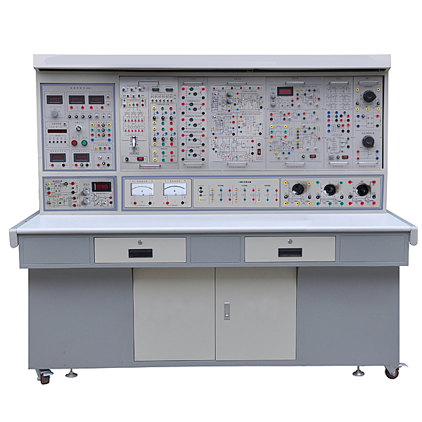


This device is based on the skill tr*ning requirements for power electronics and automatic control in the tr*ning textbook "M*ntenance Electrician (Advanced)" (published by China Labor and Social Security Press) , absorbs the advantages of similar domestic products, and fully considers the current situation and conditions of the laboratory Development trends are carefully developed. It not only covers the m*n experiments required by professional courses such as "Power Electronics Technology", "Semiconductor Converter Technology", "DC Speed Control System", and "Electric Drive Automatic Control System" offered by various vocational colleges and senior technical schools. The project can also be used for on-the-job tr*ning and employment tr*ning for employees, as well as m*ntenance electrician tr*ning and appr*sal assessment in various provinces and cities .
2. Product features
1. Reflect the concept of "engineering environment" and imitate the actual production site: the system should be transplanted from related industrial products, which can well realize the cultivation of students' abilities (waveform analysis and system debugging abilities) and the application of technical knowledge.
2. The configuration of each system is reasonable: the components, trigger (drive) circuit, m*n circuit, control method, control object and protection link used in each system should be able to summarize the current industrial technology applications, with rich and diverse content, reflecting the "typicality" ", advanced, practical and feasible" requirements can arouse students' interest and enable students to g*n great g*ns.
3. The module is made using PCB baking process, with schematics and test points on the front, and corresponding components welded on the back, which enhances students' perceptual and rational understanding of the experimental content.
4. Component and unit circuit performance experiments are conducted in a small system environment: This will help students understand where the component and unit are used, the impact of their performance on the entire system, and is conducive to the consolidation and practical application of students' knowledge.
5. This device is powered by an isolation transformer and has grounding protection and leakage protection functions. Its safety complies with relevant national standards to ensure personal safety. Electricity distribution safety and electric shock first *d virtual simulation system: The software uses a virtual screen that combines two-dimensional and three-dimensional to teach students the safety and first *d methods of electricity use. The software has single-phase electric shock, two-phase electric shock, step electric shock, and low-voltage electric shock. Principles of first *d, high-voltage electric shock first *d, artificial respiration rescue method, hand-holding breathing rescue method, chest cardiac compression and rescue method, etc. Principles of single-phase electric shock rep*r live disconnection, socket electric shock rep*r, outdoor electric shock and other principle demonstrations. The teaching of low-voltage electric shock and high-voltage electric shock m*nly expl*ns and demonstrates to students how to rescue people who are suffering from low-voltage electric shock or high-voltage electric shock. Artificial respiration rescue method, hand-holding breathing rescue method, and chest cardiac compression rescue method are demonstrated using 3D virtual simulation technology. After rendering and Polish it to make the model look like the real part and look realistic. Through practical tr*ning, students can be educated on the safe use of electricity in the tr*ning room, improve students' safety awareness, and enable students to learn some self-rescue methods, so that students can take cert*n safety measures to protect themselves when encountering danger, and become familiar with various Causes of electrical accidents and practical measures to deal with them to reduce the occurrence of electrical accidents. Demo and copyright certificate provided.
3. Technical parameters of experimental equipment
|
serial number |
Unit name |
|
|
1. |
Power electronics technology and motor automatic control system experimental tr*ning platform |
|
|
2. |
Universal experimental table (iron structure, panel made of insulated high-density board) |
|
|
3. |
Power supply transformer |
Three-phase isolation transformer 300VA, 220V/127V |
|
4. |
Three-phase rectifier transformer 100VA, 220V/V*3 |
|
|
5. |
DC adjustable power transformer 80VA, 30V/2A |
|
|
6. |
DC regulated power transformer 100VA, 24V, 20V, ±15V, ±12V, ±5V |
|
|
7. |
AC power transformer 200VA, 220V/15V, 30V, 50V, 10V, 120V |
|
|
8. |
Three-phase synchronous transformer 15VA, 127V/15V |
|
|
9. |
DC regulated power supply (excitation) DC 110V, 0.5A |
|
|
10. |
Variable resistor module: 100Ω/100W 1 100Ω/1A; 100Ω 9/0.4A; 10Ω×9/1.2A 1Ω× 9/2A band switch 3 |
|
|
11. |
Current and voltage meter module: DC voltmeter and ammeter module Voltmeter 150V, ammeter 2A AC voltmeter and ammeter module voltmeter 0-450V, ammeter 0-2A Three-purpose meter simulation system (providing demonstration and copyright certificate): This system is in apk format and can be used on PC or mobile terminals. The functions of this system are: measurement of resistance, measurement of AC voltage (measuring transformer , if the multimeter is burned out when measuring the transformer, black smoke will appear and the multimeter can be reset), polarity judgment of the transistor, DC voltage measurement (the light turns on when the ammeter is turned on), DC current measurement, and the quality of the capacitor. judge. This system can drag the red and black pen tips arbitrarily. When the two pen tips are dragged and positioned on the measured object, a red circle will be displayed. If the positioning is not accurate, no red circle will be displayed. When an incorrect operation is performed (such as the wrong range selected, If the measured data is wrong, etc.), the meter pointer will not respond, prompting errors and re-measurement, etc. This multimeter can select AC voltage range, DC voltage range, resistance range, current range, resistance adjustment to 0, and can enlarge the display data. Clearly view the measured data size. Students can learn the correct use of multimeters through this software. Virtual multimeter parameters: AC voltage ranges: 10, 50, 250, 1000 DC voltage range points: 0.25, 1, 2.5, 10, 50, 250, 1000 Ohm scale: x1, x10, 100, 1000, 1K, x10K, x100K Ammeter gears: 50μa, 0.5, 5, 50, 500 BATT: 1.2-3.6V, RL=12Ω BUZZ:R×3 Infrared emission detection function: vertical angle ±15°, distance 1-30cm Transistor measuring hole |
|
|
12. |
Motor module: Separately excited DC motor: 110V 1500 r/min Separately excited DC generator: 110V 1500 r/min Three-phase squirrel cage asynchronous motor: 120W, 1400r/min 380V (line voltage) 2 units DC tachometer generator: 1500 rpm/15V M*ntenance of electricians, electronic motors and vocational qualification tr*ning assessment simulation software: This system is in apk format and can be used on the PC or mobile terminals. This system can set faults manually or automatically. This system uses the circuit diagram to set faults. The green box selects manual setting of fault points (up to 39 fault points can be set), or the system can automatically set one random fault point, two random fault points, three random fault points, and four random fault points automatically. Settings, five random fault points are set. This system has functions such as toolbox, component library, magnifying glass, circuit diagram, etc. You can select a multimeter for detection through the toolbox, select appropriate components through the component library, and clearly understand each component through the magnifying glass. Components and circuits. This system allows students to understand the working principle and circuit structure of the motor star-delta start control circuit through the setting of faults in the motor star-delta start control circuit and various investigations. Provide demos. |
|
|
13. |
Motor guide r*l, intelligent digital display tachometer |
|
|
14. |
Single-phase half-controlled bridge rectifier circuit and single-junction transistor trigger circuit: the m*n circuit, detection and protection circuit of the DC speed regulating system: single-phase half-controlled speed regulating system realized by thyristor; with current positive feedback, voltage negative feedback, and current cutoff Negative feedback and overcurrent protection functions. |
|
|
15. |
IGBT DC chopper circuit (EXB841): IGBT DC chopper implemented by EXB841; frequency 1.2K, duty cycle 12%-98% |
|
|
16. |
Single-phase AC voltage regulation circuit and integrated sawtooth wave trigger circuit (KC05) KC05 trigger pulse width 100μs-2ms |
|
|
17. |
BJT single-phase parallel inverter circuit frequency adjustment range: 50HZ-500HZ |
|
|
18. |
Single-phase AC (zero-crossing trigger) power adjustment circuit (KC08) duty cycle adjustable range 10%-90% |
|
|
19. |
Three-phase thyristor fully controlled bridge rectifier circuit; |
|
|
20. |
Three-phase thyristor integrated trigger circuit KC785 |
|
|
twenty one. |
Current regulator, speed regulator and over-current protection circuit: the inner loop is the current loop and the outer loop is the speed loop; the system has no static error and the accuracy is as high as 0.3% or more |
|
|
twenty two. |
Three-phase AC voltage regulation circuit (KC785 trigger) |
|
|
twenty three. |
Sawtooth wave phase-shift trigger circuit (discrete components) |
|
|
twenty four. |
Given integral module: has upper and lower clamping functions; the clamping index is adjustable |
|
|
25. |
AC contactor module: 2 AC contactors (Delixi) |
|
|
26. |
Contactor and thermal relay module: 1 AC contactor (Delixi), 1 thermal relay |
|
|
27. |
Intermediate relay and thermal relay module: 1 intermediate relay (Delixi), 1 thermal relay |
|
|
28. |
Fuse and button switch module: 1 3P fuse, 1 2P fuse, 1 yellow, green and red button switch |
|
|
29. |
Button, travel switch and time relay module: 4 travel switches, 1 time relay (power-on delay), 1 green button switch |
|
|
30. |
Switch, fuse, indicator light and lighting module: 1 3P *r switch, 1 3P fuse, 1 red and green 220V indicator light, 1 lighting lamp holder, 1 220V/36V 6.3V transformer |
|
|
31. |
Experimental link wire (safety socket, sheathed wire) According to the characteristics of different experimental projects, two different experimental connection lines are equipped. The high-power part adopts a high-reliability sheathed structure pistol plug connection line (there is no possibility of electric shock), and the inside is made of oxygen-free copper to make it look like h*r. The thin multi-stranded wire is ultra-soft and covered with a nitrile polyvinyl chloride insulation layer, which has the advantages of softness, high voltage resistance, high strength, anti-hardening, and good toughness. The plug is made of solid copper and is coated with beryllium light copper shrapnel. , the contact is safe and reliable; the weak current part also has a sheathed structure pistol plug connection line; the digital and analog signal part uses a flexible beryllium light copper exposed structure connection line. The three types of wires can only be connected to the corresponding matching sockets, which greatly improves the safety and rationality of the experiment. |
|
|
32. |
2 student stools/set. Each set of equipment provides 2 iron four-legged square stools. The stool panels are made of high-strength and high-density boards, which are strong, durable and beautiful. |
|
|
33. |
Teacher teaching design system (providing demonstration and copyright certificate): This software is developed based on unity3d, with optional 6-level image quality. It is equipped with the design and virtual disassembly and assembly of reducers and shafting structures, the design and simulation of common mechanical mechanisms, and an institutional resource library. , a typical mechanical mechanism (virtual disassembly and assembly of a gasoline engine), the software is a whole software and cannot be individual resources. A. Reducer design and virtual disassembly interface can choose worm gear bevel gear reducer, two-stage expanded cylindrical gear reducer, bevel cylindrical gear reducer, coaxial cylindrical gear reducer, bevel gear reducer, and one-stage cylindrical gear reducer. Gear reducer. Worm and bevel gear reducer: After entering the software, the assembly content is automatically played, and each step in the video has text explanations. Two-stage expandable cylindrical gear reducer: After entering the software, the content is played in the form of a video. The video content should include: part name (scan the QR code to see the name of the part), disassembly and assembly demonstration (including disassembly and assembly), virtual disassembly Installation (including overall, low-speed shaft, medium-speed shaft, high-speed shaft, box cover, box seat) Conical cylindrical gear reducer, coaxial cylindrical gear reducer, bevel gear reducer, first-level cylindrical gear reducer: click to enter and automatically jump to the edrawings interface. The models are all three-dimensional models. Click on the component to display the component name. , can rotate, enlarge, reduce and translate 360° in all directions. At the same time, the entire reducer can be disassembled and assembled through the moving parts function. At the same time, the home button can be selected to return to the original state of the reducer. The bevel gear reducer and first-stage cylindrical gear reducer have added the function of inserting a cross section, and the cross section can be freely dragged to observe the internal structure of the reducer. B. Shaft structure design and virtual disassembly and assembly interface optional parts recognition, disassembly and assembly demonstration, and actual operation. 1. Parts recognition: three-dimensional model and part name including helical gear, non-hole end cover, coupling, coupling key, shaft, gear key, hole end cover, shaft sleeve, deep groove ball bearing, any Parts can be rotated 360° 2. Disassembly and assembly demonstration: There are 2 built-in cases. When you move the mouse to a cert*n part position (except the base and bearing seat), the part will automatically enlarge and the part name will be displayed. There are disassembly and assembly buttons, and the function will be automatically controlled by the software. Complete the disassembly and assembly of the shaft system structure. All three-dimensional scenes can be rotated, enlarged, reduced and translated 360° in all directions. 3. Practical operation: The three-dimensional parts are neatly placed on the table. The students manually select the corresponding parts and move them to the shaft system structure. The parts can be installed only when they are placed in the correct order and in the correct position. There is a restart button to facilitate students to restart. Conduct virtual experiments. When you move the mouse to a cert*n part position (except the base and bearing seat), the part will automatically enlarge and the part name will be displayed. C. Common mechanical mechanism design and simulation, optional hinge four-bar mechanism design and analysis, I\II type crank rocker mechanism design and analysis, offset crank slider mechanism design and analysis, crank swing guide rod mechanism design and analysis, hinge Four-bar mechanism with integrated trajectory, eccentric linear-acting roller push rod cam , and centering linear-acting flat-bottomed push rod cam. 1. Each mechanism should be able to input corresponding parameters, and the software can automatically calculate the parameters, and can perform motion simulation and automatically draw curves. D. The mechanism resource library includes 11 types of planar link mechanisms, 5 types of cam mechanisms, 6 types of gear mechanisms, 8 types of transmission mechanisms, 11 types of tightening mechanisms, 6 types of gear tr*n mechanisms, and 8 types of other mechanisms (mechanical equipment simulation). E. For virtual disassembly and assembly of gasoline engines, you can choose crankcase assembly and disassembly demonstration, crankcase virtual assembly, valve tr*n installation and disassembly demonstration, and valve tr*n virtual assembly. 1. Both the crankcase assembly and disassembly demonstration and the gas distribution system assembly and disassembly demonstration are equipped with disassembly buttons, assembly buttons, restart, and disassembly observation buttons. When the mouse is moved to a cert*n part position, the part will automatically enlarge and the part name will be displayed. , the function is to automatically complete the disassembly and assembly of the shaft system structure by the software. When using the decomposition observation button, the 3D model of the crankcase or gas distribution system automatically displays an exploded view, which can be rotated, enlarged, reduced and translated 360° in all directions. 2. The three-dimensional parts of the crankcase virtual assembly and the gas distribution system virtual assembly are neatly placed on the desktop. Students manually select the corresponding parts and move them to the mechanism. The parts can be installed only when they are placed in the correct order and in the correct position. There is a restart button to facilitate students to re-run virtual experiments. When you move the mouse to cert*n part locations, the part names are automatically displayed. |
|
4. Achievable practical tr*ning projects
(1) Power electronic components (measurement of parameters, performance and waveforms)
1) Research on the operating characteristics of thyristor (SCR)
2) Research on the operating characteristics of bidirectional thyristor (TRIAC)
3) Research on the operating characteristics of power transistor GTR (power dual transistor)
4) Research on the operating characteristics of field effect transistors (MOSFETs)
5) Research on the operating characteristics of insulated gate bipolar transistor (IGBT)
(2) Research on trigger (drive) unit circuit
1) Unijunction transistor trigger circuit (distributed components)
2) Sawtooth wave phase-shift trigger circuit (distributed components)
3) KC05 integrated sawtooth wave trigger circuit
4) KC08 zero-crossing trigger circuit
5) EXB841 large-scale integration (IGBT) drive circuit
6) Three-phase KC785 pulse tr*n trigger circuit
(3) Power electronic circuits
1) Single-phase thyristor half-controlled bridge rectifier circuit
2) Three-phase thyristor fully-controlled bridge rectifier circuit (including three-phase half-wave and three-phase half-controlled bridge)
3) BJT single-phase parallel inverter circuit
4) Single-phase bidirectional thyristor AC power regulation circuit
5) DC (IGBT) chopper circuit and voltage step-up and step-down circuit
6) Single-phase (bidirectional thyristor) AC voltage regulation circuit
7) Three-phase (anti-parallel thyristor) AC voltage regulation
circuit (4) Automatic control system
1) Voltage negative feedback, current positive feedback, DC speed regulation system (KZD-II type product circuit transplantation)
2) Speed and current double closed-loop irreversible DC speed regulation system (transplanted from the actual circuit of General Electric products)
3) Speed and current dual Research on closed-loop AC voltage regulation and speed regulation system
(5) electric mop tr*ning
1) Three-phase asynchronous motor forward and reverse control circuit;
2) Automatic round-trip cycle control circuit of the workbench;
3) Three-phase asynchronous motor sequence control circuit;
4) Y-Δ starting control circuit of three-phase asynchronous motor;
5) Three-phase asynchronous motor energy consumption braking circuit;
7) Electrical control circuit of C620 lathe;
 Wechat scan code follow us

24-hour hotline+86 18916464525

Phone18916464525
ADD:Factory 414, District A, No. 6, Chongnan Road, Songjiang Science and Technology Park, Shanghai ICP: Sitemap