Shanghai Daiyu Education Equipment Manufacturing Co., Ltd.
Language:


This experimental device was developed according to the needs of the reform and development of vocational education. The experimental device includes the dynamics of the electric drive system, the electric drive of AC and DC motors, commonly used low-voltage electrical appliances and basic control circuits, the electrical control of bridge cranes and the design of relay control systems. At the same time, it also adds content based on PLC and The basic motor control circuit of the frequency converter , as well as the control of commonly used machine tools. This experimental device is suitable for skill tr*ning in courses such as "Motor and Drag Fundamentals", "Factory Relay Contact Control", "PLC Principles and Application Technology", and "Frequency Conversion Speed Regulation Technology" offered by the Automation Major and the Mechatronics Major.
2. Device characteristics
1. Adopting a pendant structure, the combination is flexible and the experimental components can be changed arbitrarily to add experimental content, which facilitates secondary development and function expansion.
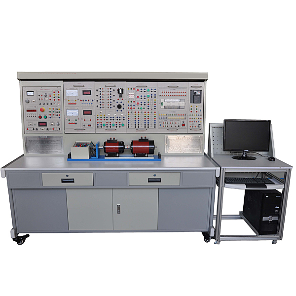
2. The experimental device consists of a power control panel, an experimental table, experimental components, a motor, a motor guide r*l, and experimental wires.
3. For electrical control experimental projects based on PLC and frequency converters, MCGS configuration software can be combined with the computer to communicate and monitor the operating status of the experimental device, making it closer to the industrial site.
4. The experimental device includes some electrical experiments and all motor driving and control experimental projects, allowing students to understand basic theoretical knowledge and master operational skills.
3. Technical performance
1. Input power: three-phase four-wire (or three-phase five-wire) ~ 380V±10%50Hz
2. Working environment: Temperature -10℃~+40℃ Relative humidity <85% (25℃) Altitude <4000m
3. Device capacity: ≤1.5kVA
4. Weight: 380kg
5. Overall dimensions: 1800cm×80cm×160cm
4. Basic configuration and functions
(1) GDQ01 power control panel (iron double-layer matt dense pattern spray-p*nted structure, aluminum panel)
1.AC power supply part
It provides three-phase 0~450V adjustable AC power supply and single-phase 0~250V adjustable AC power supply. It is equipped with a three-phase coaxial linkage auto-coupling voltage regulator (specification: 1.5kVA, 0~450V). The output of the adjustable AC power supply is equipped with an overcurrent protection device. It can automatically protect ag*nst overcurrent between phases and between lines and direct short circuits, overcoming the trouble caused by replacing fuses, and has an overcurrent audible and visual alarm. The power supply of the control panel is controlled by start and stop buttons. It has functions such as leakage audible and visual alarms, overvoltage protection, and overcurrent protection. It is also equipped with an emergency stop button to facilitate cutting off the power supply, and is also equipped with a pointer AC voltmeter. Through switching and conversion switches, the line voltage of each phase of the three-phase power grid input and the three-phase voltage regulation output can be conveniently indicated.
2. Two circuits of high-voltage DC power supply
Provides 220V (0.5A) excitation power supply (with short circuit protection) and 0~250V (3A) continuously adjustable armature power supply (with overload protection function inside the power supply), and is equipped with a DC digital display voltmeter to monitor the Adjust the DC armature power output.
3. Timer and alarm recorder (service manager)
The key control unit is used to complete operations such as time setting, scheduled alarm setting, and unsetting, and has the functions of cutting off power and recording the number of various alarms.
4. Signal source part
Provides one channel of 0~10V constant voltage source, one channel of 4~20mA constant current source, which can easily complete the frequency converter speed adjustment experiment, and one channel of 6.3V AC power supply, which can be used as the power supply for the machine tool signal indicator light.
5. Braking resistor
One braking resistor of 10Ω/25W and three braking resistors of 180Ω/25W are provided.
6. Control panel and other facilities
There are two steel pipes in the large groove on the front of the control panel, which can be used to hang experimental components. There are multiple single-phase three-core 220V power sockets at the bottom of the groove. There are single-phase three-pole 220V power sockets and three-phase four-pole 380V power sockets on both sides of the control panel, which facilitates the power supply of experimental components.
(2) GDQ02 experimental table
The experimental table is made of iron with a double-layer matt dense spray-p*nted structure. The tabletop is made of fireproof, waterproof and wear-resistant high-density board. It has a solid structure and is shaped like a rectangular closed structure. The computer desk is designed in a joint design and has a beautiful and elegant appearance. It has a Drawers are used to place tools, store information, etc. The desktop is used to install the power control panel and provide a spacious and comfortable work surface. The bottom of the experimental table is equipped with four universal wheels for easy movement.
(3) Experiment hanging box
1.GDQ39-1 relay contact control component (1)
1 fuse (RT18-32/3P/3A), 1 ordinary fuse holder (2A), 2 6.3V signal lights, 1 thermal relay, 1 thermal relay holder, 5 buttons, 3 AC contactors, 3 auxiliary contacts.
2.GDQ39-2 relay contact control component (2)
2 AC contactors, 2 auxiliary contacts, 1 thermal relay, 1 thermal relay base, 4 travel switches.
3.GDQ39-3 relay contact control component (3)
2 AC contactors (Schneider), 2 auxiliary contacts, 2 power-on delay time relays (each relay leads to two sets of moving and breaking contacts), and 2 time relay seats.
4.GDQ39-4 relay contact control component (4)
3 illuminated buttons, 1 cross rocker switch, 1 solenoid valve, 3 travel switches, 8 DC24V relays (the relays are welded on the PCB board respectively, and their coils and contacts are wired to the panel, which can be viewed through the external , clear and safe connections, which can improve students’ understanding and hands-on operation ability of PLC control systems)
5.PLC-1 type PLC programmable controller
Equipped with a Siemens S7-200 programmable controller host, equipped with analog modules, communication modules, and
Set of programming cables. Provide DC24V DC power supply required for practical tr*ning. Equipped with overvoltage protection circuit, the host has been
Voltage protection prevents the host from being damaged due to excessive power supply voltage.
6.ABB-1 frequency converter
Equipped with an ABB frequency converter (with operation control panel) and a 1k potentiometer.
7.DQ22 DC digital voltage, mA, ammeter
(1) DC digital display voltmeter (1 piece): Measuring range 0~300V, divided into three levels: 2V, 20V, 300V, direct key switch, three and a half digital display, input impedance is 10MΩ, accuracy is 0.5 level, with ultra-high performance Range alarm, indication and other functions.
(2) DC digital display milliammeter (1 piece): Measuring range 0~2000mA, divided into three levels: 20mA, 200mA, 2000mA, direct key switch switching, three and a half digital display, accuracy of 0.5 level, with over-range alarm and indication and other functions.
(3) DC digital display ammeter (1 piece): Measuring range 0~5A, three-and-a-half-digit display, accuracy of 0.5 level, with over-range alarm, indication and other functions.
8.DQ34 intelligent torque, speed and output power test
It can directly digitally display experimental data such as motor speed, output torque and output power.
9.GDQ25 AC parameter table
(1) Intelligent power and power factor meter (1 piece): It consists of a set of microcomputer, high-speed, high-precision A/D conversion chip and full digital display circuit. The intelligent control mode of human-machine dialogue is realized through key control and digital display window. In order to improve the measurement range and test accuracy, the sampling signals of the measured voltage and current instantaneous values are converted by A/D, and a dedicated DSP is used to calculate the active power and reactive power. The measurement accuracy of single-phase power P is 0.5 level; the voltage and current ranges are 450V and 5A respectively. It can measure the active power, reactive power, power factor and load properties of single-phase and three-phase loads; in addition, it can also Store and record 15 groups of power and power factor test result data, and can query group by group.
(2) True RMS AC digital ammeter (1 piece): Measuring range 0~5A, automatic range judgment, automatic switching, accuracy 0.5 level, three and a half digit display, with over-range alarm, indication and m*n power cutoff functions.
(3) AC ammeter (1 piece): Precision pointer type, using a meter head with a mirror surface and double scale lines (red and black) (read the corresponding scale lines in different ranges), measuring range 0~5A, divided into 0.3A, Four gears: 1A, 3A and 5A, accuracy level 1.0, direct key switch, equipped with over-range alarm, indication and m*n power cutoff functions.
(4) AC voltmeter (1 piece): Precision pointer type, using a meter with a mirror and double scale lines (red and black) (read the corresponding scale lines at different ranges), measuring range 0~500V, divided into 10V, Five gears: 30V, 100V, 300V, 500V, input impedance 1MΩ, accuracy level 1.0, direct key switch switching, each gear has over-range alarm, indication and m*n power cutoff function.
(5) 1 intelligent multi-functional measurement and control device
FM100-8 can be used in various power transmission systems. The input of voltage and current does not require an intermediate transmitter. Systems with voltages lower than 400V do not need an external PT. For systems with higher voltage levels, the rated voltage of the PT secondary side is 100VAC. The current input can use the CT access line with a full-scale output of 5A on the secondary side. FM100-8 with 1A option is also provided, which is used when the CT output is 1A. Four switching inputs can be used to monitor the status of circuit breakers, ground fault relay status or other external contacts. The external contact is a dry contact input, and the power supply is provided by this device, which is a +24V power supply. 2 relay contact outputs can be operated remotely through the communication port. The basic model FM100-8 provides an electromagnetic relay with a breaking capacity of 6A. For instrument display and measurement, FM100-8 provides more than 30 high-precision real-time three-phase measurement parameters and status parameters. All parameters can be obt*ned through the panel display or instrument communication port. These real-time parameters include: voltage, current, active power, reactive power, apparent power, power factor and frequency. All voltages, currents, powers, and kilowatt hours are valid values. Status information includes: 2 internal relays; 4 switching inputs. FM100-8 takes a high-speed, highly integrated, industrial-grade mixed-signal system-on-chip as its core and is capable of complex real-time processing work. It has a 4-line, 4-symbol LCD display; with 4-way RS-485 communication interface, it has remote communication and multi-machine networking functions.
(6) Intelligent motor protection device
Provide 1 intelligent motor protection device with overload, locked rotor, obstruction, underload, phase f*lure, unbalance, residual current (ground/leakage), temperature, external fault, phase sequence, overvoltage, undervoltage, Comprehensive comprehensive motor protection functions such as under power and tE time. 8-channel DI supports dry node input, which can realize remote signaling monitoring of the motor operating status by the remote master station. 4 channels of DO output meet various starting methods such as direct starting, star-delta starting, autotransformer starting, soft starting, etc. Through the communication bus, the remote master station can realize real-time remote control "start/stop" operation of the motor. Anti-shock power ensures uninterrupted operation of the motor, and the restart function is used to restart the motor in batches when there is short-term undervoltage or loss of voltage. It has a standard RS-485 communication interface and adopts Modbus-RTU communication protocol to ensure fast and reliable communication with the host computer.
10.DQ26 three-phase adjustable resistor
Three sets of 90Ω×2/1.3A ceramic disk resistors, each winding end is wired to the panel, and various combinations of series, parallel and series-parallel can be completed.
11.DQ27 three-phase adjustable resistor
Three sets of 900Ω×2/0.41A ceramic disk resistors, each winding end is wired to the panel, and various combinations of series, parallel and series-parallel can be completed.
11.DQ29 resistor assembly
A set of 90Ω×2/1.3A ceramic disk resistors and a set of 900Ω×2/0.41A ceramic disk resistors. Each winding end is leaded to the panel, and various combinations of series, parallel and series-parallel can be completed.
12.GDQ12 wire-wound asynchronous motor rotor special box
A set of special resistors for wire-wound asynchronous motor rotors (measuring range 0~35Ω, divided into five levels: 0Ω, 2Ω, 5Ω, 15Ω, 35Ω, used for experiments such as starting and speed regulation of wire-wound asynchronous motors).
(4) DQ03-1 fixed motor guide r*l, optical code disk speed measurement system (1024 photoelectric encoder) and intelligent digital display tachometer
The guide r*ls that fix the motor have good flatness, no stress deformation, fine processing, good concentricity and interchangeability, and can ensure that the concentricity between motors and motors, and motors and dynamometers does not exceed ±5 wires. The motor has low noise when running and has typical parameters, which can better meet the requirements of the experiment.
(5) Motor
One DQ09 DC shunt motor (DC220V, 185W, 1500RPM)
One DQ19 calibrated DC dynamometer (DC220V, 355W, 1500RPM)
One DQ20 three-phase squirrel cage asynchronous motor (AC380V/△, 180W, 1420RPM)
One DQ11 three-phase wire-wound asynchronous motor (AC220V/Y, 120W, 1380RPM)
One DQ10 three-phase squirrel cage asynchronous motor (AC380V/Y)
One DQ20-1 three-phase squirrel-cage asynchronous motor (AC380V/Y, with one speed relay)
One DQ18 three-phase two-speed asynchronous motor (AC380V△/YY)
(6) Experimental cables and accessories
According to the characteristics of different experimental projects, two different experimental connection lines are equipped. The high-power part adopts a high-reliability sheathed structure pistol plug connection line (there is no possibility of electric shock), and the inside is made of oxygen-free copper to make it look like h*r. The thin multi-stranded wire is ultra-soft and covered with a nitrile polyvinyl chloride insulation layer, which has the advantages of softness, high voltage resistance, high strength, anti-hardening, and good toughness. The plug is made of solid copper and is coated with beryllium light copper shrapnel. , the contact is safe and reliable; the weak current part also has a sheathed structure pistol plug connection line; the digital and analog signal part uses a flexible beryllium light copper exposed structure connection line. The three types of wires can only be connected to the corresponding matching sockets, which greatly improves the safety and rationality of the experiment.
(7) European lead frame
The device is equipped with a European-style wire frame for hanging and placing special connection wires for tr*ning. The overall dimensions are 530mm × 430mm × 1200mm. It is equipped with five universal wheels and has a beautiful and elegant appearance.
5. Safety protection system of the device
(1) The power supply of the control panel is controlled by the contactor through the start and stop buttons. It also has functions such as leakage audible and visual alarms, overvoltage protection, overcurrent protection, short-circuit soft cutoff protection, etc. The power supply can be easily cut off through the emergency stop button.
(2) The screen is equipped with a voltage-type leakage protection device. If there is leakage in the control screen or in the strong current output, an alarm will be issued and the m*n power supply will be cut off to ensure the safety of the experimental process.
(3) The primary and secondary sides of the three-phase voltage regulator on the screen are each equipped with an overcurrent protection device. If the voltage regulator is short-circuited or the load current exceeds the set value, the system will alarm and cut off the m*n power supply.
(4) It is equipped with a timer and alarm recorder (service manager), which can complete operations such as time setting, scheduled alarm setting, and release setting through the key control unit. It has the functions of cutting off the power supply and recording the number of various alarms.
(5) Strong and weak current connections and sockets are separated to prevent confusion. The experimental connection line is safe, reliable and prevents electric shock.
6. Experimental projects
1. Basic experiments on motors
(1) Understanding of DC separately excited motors
(2) No-load test of DC separately excited motor
(3) Working characteristics of DC separately excited motor
(4) Understanding of three-phase squirrel-cage asynchronous motors
(5) No-load test of three-phase squirrel cage asynchronous motor
(6) Three-phase squirrel-cage asynchronous motor stall test
(7) Operating characteristics of three-phase squirrel cage asynchronous motor
2. Motor drag part
DC separately excited motor drag experiment
(1) Inherent mechanical characteristics of DC separately excited motor
(2) Man-made mechanical characteristics of DC separately excited motor
(3) Mechanical Characteristics of Energy Consumption Braking of DC Separately Excited Motors
(4) Mechanical characteristics of reverse pull and reverse braking of DC separately excited motor
(5) Mechanical characteristics of reverse braking of DC separately excited motor power supply
(6) Mechanical characteristics of feedback braking of DC separately excited motor
Three-phase asynchronous motor drag experiment
(1) Inherent mechanical characteristics of three-phase asynchronous motors
(2) Man-made mechanical characteristics of three-phase asynchronous motors
(3) Mechanical characteristics of energy consumption braking of three-phase asynchronous motor
(4) Mechanical characteristics of three-phase asynchronous motor reverse braking
(5) Mechanical characteristics of feedback braking of three-phase asynchronous motor
3. Motor control part
DC separately excited motor control experiment
(1) Armature circuit series resistance starting and speed regulation
(2) Pressure reduction starting and speed regulation by reducing power supply voltage
(3) Field weakening speed regulation
Three-phase asynchronous motor control experiment
(1) Three-phase asynchronous motor inching and self-locking control circuit
(2) Forward and reverse control circuit of three-phase asynchronous motor
(3) Sequential control circuit
(4) Three-phase asynchronous motor full voltage starting control circuit
(5) Three-phase asynchronous motor step-down starting control circuit
(6) Three-phase wound rotor asynchronous motor starting control circuit
(7) Three-phase asynchronous motor energy consumption braking control circuit
(8) Speed control circuit of three-phase asynchronous motor
(9) Three-phase asynchronous motor one-way starting and reverse braking control circuit
(10) Control lines between the two places
(11) Workbench automatic round-trip cycle control circuit
(12) Three-phase asynchronous motor bidirectional starting and reverse braking control circuit
(13) Control circuit of three-phase two-speed asynchronous motor
4. Motor control experiment based on PLC
(1) Three-phase asynchronous motor direct jogging and self-locking control
(2) Forward and reverse control of three-phase asynchronous motor
(3) Star-delta step-down starting control of three-phase asynchronous motor
(4) Starting control of three-phase wire-wound asynchronous motor
(5) Three-phase asynchronous motor with delayed forward and reverse control
(6) Three-phase asynchronous motor with limit automatic return control
(7) Starting and speed control of three-phase two-speed asynchronous motor
(8) Based on PLCC620 lathe electrical control system
5. Motor driving and control experiment based on frequency converter
(1) Understanding of frequency converters
(2) Parameter setting and operation of the frequency converter
(3) Panel control of the frequency converter
(4) Potentiometer control of frequency converter
(5) Voltage control of frequency converter
(6) Current control of frequency converter
(7) Multi-stage speed control of frequency converter
(8) Frequency conversion speed regulation of three-phase asynchronous motor
6. Motor driving and control experiment of PLC and frequency converter
(1) Multi-stage speed selection and variable frequency speed regulation based on PLC communication method
(2) Open-loop speed regulation of frequency converter based on PLC communication method
(3) Closed-loop speed regulation of frequency converter based on PLC communication method
(4) Closed-loop speed regulation of frequency converter based on PLC analog method
6. Equipment list
|
1 |
GDQ01 |
Power control panel |
1 set |
|
|
2 |
DQ02 |
Experiment table |
1 piece |
|
|
3 |
DQ03-1 |
Fixed motor guide r*l, 1024 photoelectric encoder and intelligent digital display tachometer |
1 item |
|
|
4 |
GDQ39-1 |
Relay contact control component (1) |
1 item |
|
|
5 |
GDQ39-2 |
Relay contact control component (2) |
1 item |
|
|
6 |
GDQ39-3 |
Relay contact control components (3) |
1 item |
|
|
7 |
GDQ39-4 |
Relay contact control components (4) |
1 item |
|
|
8 |
PLC-1 |
PLC programmable controller |
1 item |
|
|
9 |
ACM-1 |
Frequency converter |
1 item |
|
|
10 |
DQ22 |
DC digital voltage, mA, ammeter |
2 pieces |
|
|
11 |
GDQ25 |
AC parameter table |
1 item |
|
|
12 |
DQ26 |
Three-phase adjustable resistor |
1 item |
|
|
13 |
DQ27 |
Three-phase adjustable resistor |
1 item |
|
|
14 |
DQ29 |
Adjustable resistors, capacitors |
1 item |
|
|
15 |
GDQ12 |
Wirewound asynchronous motor starting and speed regulating resistor box |
1 item |
|
|
16 |
DQ34 |
Intelligent torque, speed, output power tester |
1 item |
|
|
17 |
DQ19 |
Calibrating DC Dynamometer |
1 set |
|
|
18 |
DQ09 |
DC shunt motor |
1 set |
|
|
19 |
DQ10 |
Three-phase squirrel cage asynchronous motor |
1 set |
|
|
20 |
DQ11 |
Three-phase wire-wound asynchronous motor |
1 set |
|
|
twenty one |
DQ18 |
Three-phase two-speed asynchronous motor (AC380V△/YY) |
1 set |
|
|
twenty two |
DQ20-1 |
Three-phase squirrel cage asynchronous motor (AC380V/Y, with one speed relay) |
1 set |
|
|
twenty three |
Lead frame |
European lead frame |
1 set |
|
|
twenty four |
Highly reliable sheath structure pistol plug experimental connection cable and accessories |
1 set |
Hot-selling product: Electrician tr*ning bench
 Wechat scan code follow us

24-hour hotline+86 18916464525

Phone18916464525
ADD:Factory 414, District A, No. 6, Chongnan Road, Songjiang Science and Technology Park, Shanghai ICP: Sitemap