Shanghai Daiyu Education Equipment Manufacturing Co., Ltd.
Language:


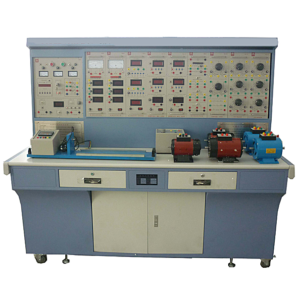


" Motor and electrical technology experimental device" is a novel comprehensive experimental device designed by our company. It integrates the current "electrical machinery", "motor and drag", "control micromotor", "motor control" and "continuation" of colleges and universities in China. Requirements for the experimental syllabus of courses such as "Electrical Contact Control" and "Factory Electrical Control". It is especially suitable for the upgrading and transformation of existing motor and electrical technology experimental equipment in colleges and universities. It also provides ideal experimental equipment for new or expanded laboratories and rapid opening of experimental courses in secondary vocational schools, vocational and technical colleges, etc., and provides ideal experimental equipment for teachers or It provides good experimental conditions for graduate students to develop new experiments or conduct scientific research.
2. Features
1. Strong comprehensiveness This device integrates all the experimental projects of electrical and electrical courses in various domestic colleges and universities.
2. It is highly adaptable and can satisfy the experimental teaching of corresponding courses in various schools. The depth and breadth of experiments can be flexibly adjusted according to needs, and popularization and improvement can be organically combined according to the teaching process. The device adopts a component structure and is easy to replace. If you need to expand functions or develop new experiments, you only need to add components and it will never be eliminated.
3. The complete set is complete, including instruments, special power supplies, motors and other experimental components, as well as special wires for experimental connections. The performance and specifications of the supporting components are closely combined with the needs of the experiment.
4. Strong intuitiveness. Each experimental pendant adopts a separated structure, with clear component panel diagrams and clear diagrams. Each pendant has clear tasks and is easy to operate and m*nt*n.
5. The highly scientific device occupies a small area, saving experimental space and reducing infrastructure investment; the supporting small motors are specially designed to simulate the characteristics and parameters of small and medium-sized motors; small motors consume less power and save energy; experimental noise Small, neat and beautiful, improving the experimental environment; the electrical control experiment is rich in content and reasonably designed. In addition to deepening theoretical knowledge, it also lays a good foundation for students to enter the society; the measuring instruments adopt pointer type (with over-range alarm, etc.), digital type , intelligence and human-machine dialogue are combined, and the configuration is closely combined with the needs of teaching experiments to modernize the device measurement methods; it is equipped with a timer and alarm recorder to provide a unified standard for the assessment of students' experimental skills.
6. The control panel has strong openness and power supply isolation (floating design), and is equipped with voltage-type leakage protection devices and current-type leakage protection devices to ensure the safety of the operator; each power output has monitoring and short-circuit protection functions. Convenient; each measuring instrument has a protection function. The entire device is carefully designed, guaranteed by reliable component quality and reliable technology, and has excellent product performance. All of these create conditions for open experiments and are conducive to improving students' ability to analyze and solve problems.
3. Technical performance
1. Input power supply: three-phase four-wire (or three-phase five-wire) ~ 380V±10%50Hz
2. Working environment: temperature -10℃~+40℃, relative humidity <85% (25℃), altitude <4000m
3. Device capacity: <1.5KVA
4. Overall dimensions: 1870mm×700mm×1600mm
5. Virtual multimeter parameters: AC voltage range points: 10, 50, 250, 1000; DC voltage range points: 0.25, 1, 2.5, 10, 50, 250, 1000; Ohm range points: x1, x10, ,100,,1000,,1K,x10K,x100K; Ammeter range: 50μa, 0.5, 5, 50, 500; BATT: 1.2-3.6V, RL=12Ω; BUZZ: R×3; Infrared emission detection function: vertical Angle ±15°, distance 1-30cm; triode measuring hole.
4. Experimental projects
1. DC motor
1) DC motor understanding experiment (cold resistance measurement, nameplate value understanding, starting, commutation, speed control)
2) DC compound-excited generator experiment (research on compound-excited generator characteristics)
3) DC shunt motor experiment (research on shunt motor characteristics)
4) DC series motor experiment (research on series motor characteristics)
2. Transformer experiment
1) Single-phase transformer experiment (no-load/load/short-circuit experiment)
2) Three-phase transformer experiment (no-load/load/short-circuit experiment)
3) Connection group and asymmetric short circuit of three-phase transformer
4) Three-phase three-coil core transformer
5) Parallel operation of single-phase transformers
6) Parallel operation of three-phase transformers
3. Asynchronous motor experiment
1) Working characteristics of three-phase squirrel cage asynchronous motor
2) Starting and speed regulation of three-phase asynchronous motor
3) Mitsubishi variable frequency speed motor experiment
4. Synchronous motor experiment
1) Operating characteristics of three-phase synchronous generator
2) Grid-connected operation of three-phase synchronous generator
3) Three-phase synchronous motor
4) Determination of three-phase synchronous motor parameters
5. Determination of mechanical characteristics of electric motors
1) Mechanical characteristics of DC separately excited motors under various operating conditions (four-quadrant operation)
2) Mechanical characteristics of three-phase asynchronous motors under various operating conditions
3) Surveying and mapping of three-phase asynchronous motor MS curve
6. Control motor experiment
1) Rotary encoder experiment
2) DC servo motor experiment
3) Mitsubishi AC servo motor experiment
7. Relay contact control and electric drag (electrical control)
1) Three-phase asynchronous motor inching and self-locking control circuit
2) Three-phase asynchronous motor forward and reverse control circuit
3) Sequence control circuit
4) Three-phase squirrel cage asynchronous motor step-down starting control circuit
5) Three-phase wire Control circuit for starting of winding asynchronous motor
6) Control circuit for energy consumption braking of three-phase asynchronous motor
7) Control circuit for one-way starting and reverse braking of three-phase asynchronous motor
8) Control circuit between two places
9) Workbench round trip Cycle control circuit
10) Electrical control circuit of C620 lathe
11) Electrical control circuit of electric hoist
(12) Control circuit of two-speed asynchronous motor
(13) Electrical control circuit of M7130 surface grinder
(14) Debugging of analog control circuit of X62W milling machine Analysis
5. Introduction to device configuration
1. DQ01B power control panel (iron plastic spray structure, aluminum panel)
(1) AC power supply
Provides three-phase 0~450V adjustable AC power supply, and at the same time can obt*n single-phase 0~250V adjustable power supply (equipped with a three-phase linkage auto-coupling voltage regulator (specification 1.5KVA, 0~450V), overcoming the problem of three single-phase There are many disadvantages to using a ch*n structure or a gear structure for phase voltage regulators). The output of the adjustable AC power supply is equipped with over-current protection technology, which can automatically protect phase-to-phase and line-to-line overcurrent and direct short circuit. Equipped with three pointer AC voltmeters, which indicate the three-phase grid voltage and the three-phase voltage regulation voltage through the switch.
(2) Two circuits of high-voltage DC power supply
Provides one set of 220V (0.5A) excitation power supply and 0~250V (3A) continuously adjustable regulated armature power supply (with internal overcurrent and soft cutoff automatic recovery protection functions), and is equipped with a DC digital display voltmeter and switch switch.
(3) Five major systems of personal safety protection
It is equipped with a set of three-phase isolation transformers (the three-phase power supply passes through the key switch and contactor, then to the isolation transformer, and then is output through the three-phase voltage regulator) to isolate the output from the power grid and play a cert*n protective role in personal safety;
It is equipped with a current leakage protector. If there is leakage in the control panel and the leakage current exceeds a cert*n value, the power supply will be cut off. The strong current connecting wires and sockets adopt a fully enclosed structure, which is safe, reliable and prevents electric shock.
It is equipped with a voltage type leakage protector. If there is leakage during the experiment, the power supply will be cut off.
The strong current connecting wires and sockets adopt a fully enclosed structure, which is safe, reliable and prevents electric shock.
(4) Instrument protection system
There are multiple signal sockets connected to the instrument. If the instrument exceeds the range, it can alarm and play a good protection role for the instrument.
(5) Timer and alarm recorder (service manager): It has the functions of setting time, alarming on time, cutting off power and recording the number of various alarms.
(6) There are two steel pipes in the large groove on the front of the control panel, which can hang instruments and experimental components. There are multiple small round single-phase three-core 220V power sockets at the bottom of the groove for power supply to instruments and other components. There are three-pole 220V power sockets and three-phase four-pole 380V power sockets on both sides of the control panel. There is a 220V, 40W fluorescent lamp for experimental bench
lighting. 2. DQ02 experimental table
The experimental table is made of iron with a double-layer matt dense spray-p*nted structure. The tabletop is made of fireproof, waterproof and wear-resistant high-density board. It has a solid structure and is shaped like a rectangular closed structure. It has a beautiful and elegant appearance; it is equipped with two large drawers and cabinet doors. , used to place tools, store pendants and information, etc. The desktop is used to install the power control panel and provide a spacious and comfortable work surface. The experimental table is also equipped with four universal wheels and four fixed adjustment mechanisms, which are easy to move and fix, and are conducive to the layout of the laboratory.
3. DQ03-1 fixed motor guide r*l, 4 photoelectric encoder speed measurement system and intelligent digital display tachometer
Including speed measurement system and guide r*ls for fixing the motor, etc. The guide r*l has good flatness, no stress deformation, fine processing, good concentricity, and good interchangeability. It can ensure that the concentricity between motors and motors, and motors and dynamometers does not exceed ±5 wires. The motor operation noise is small, and the experiment The parameters are typical and can better meet the experimental requirements.
4. DQ05 three-phase transformer
It consists of three identical single-phase transformers, with the primary side 220V/0.35A and the secondary side 55V/1.4A.
5. DQ06 three-phase core transformer
A three-phase three-winding transformer with a three-column iron core structure. Each column of iron core is equipped with three windings of high voltage, medium voltage and low voltage. Its ratings are 220V/0.4A, 63.6V/0.8A and 55V/1.6A respectively.
6. DQ07 DC compound-excited generator (Un=DC200V, IN=0.5A, PN=100W, n=1600RPM, insulation class E).
7. DQ08 DC series motor
8. DQ09 DC parallel (separately) excited motor (Un=DC220V, IN=1.1A, PN=185W, n=1500RPM, insulation grade E)
9. DQ10 three-phase squirrel cage asynchronous motor (AC3800V/220V, connection Y/Δ, speed 1420RPM, power 100W, current 0.5A, insulation grade E)
10. DQ11 three-phase wire-wound asynchronous motor (AC220V, connection Y, speed 1380RPM, power 120W, current 0.6A, insulation grade E)
11. GDQ12 wire-wound asynchronous motor starting and speed regulating resistor box
Provides a set of rotor starting and speed regulating resistors for three-phase wound asynchronous motors with five-speed coaxial adjustment of 0, 2, 5, 15 and 35.
12. DQ14 three-phase synchronous motor
When used as a motor, 220V/Y, 0.35A, 90W, 1500r/min; when used as a generator, 220V/Y, 0.45A, 170W, 1500r/min.
13. DQ19 calibrated DC dynamometer (220V, 2.2A, 355W, 1500r/min)
It can be used as both a motor and a dynamometer. When used as a motor, it can be used as the prime mover of a generator or to drag the motor to complete the four-quadrant test. When used as a dynamometer, due to the special design of the motor, the capacity is 2 to 3 times that of the motor under test, and calibrated by precision instruments, it can well complete the test of the load output torque of the motor under test.
14. DQ20 three-phase squirrel cage motor (△220V) (for "relay contact control" experiment)
15. DQ22 DC digital voltage, milliampere, ammeter (three pieces) and
one DC digital display voltmeter. It is designed using ICL company's high-performance AD converter and high-speed MPU unit. It realizes human operation through keying and digital display window. machine dialogue function control mode. It has automatic and manual ranges, and the measuring range is 0-300V. Manual ranges are: 2V, 20V, 300V. The measurement accuracy is 0.5 level. It has data storage and query functions. It has functions such as over-range alarm and indication.
A DC digital display milliamp meter is designed using ICL's high-performance AD converter and high-speed MPU unit. It realizes human-machine dialogue function control mode through key control and digital display window. With automatic and manual range, measuring range: 0-2000mA. Manual ranges are: 20mA, 200mA, 2000mA. The measurement accuracy is 0.5 level. It has data storage and query functions. It has functions such as over-range alarm and indication.
A DC digital display ammeter with a measuring range of 0 to 5A, a three-and-a-half-digit display, an accuracy of 0.5, and a short-circuit protection function.
16. DQ25 single and three-phase intelligent power and power factor meter
is designed by 24-bit dedicated DSP, 16-bit high-precision AD converter and high-speed MPU unit. It realizes human-machine dialogue function control mode through key control and digital display window. The software adopts RTOS design ideas and is equipped with PC monitoring software to enhance analysis capabilities. It can measure two single-phase powers P1 and P2 at the same time. The three-phase power is equal to the sum of the two-channel powers (the two-meter method measures the total three-phase power). The power measurement accuracy is level 1.0, the power factor measurement range is 0.3-1.0, the voltage and current range is 450V and 5A, and it can automatically determine the load properties (inductive display "L", capacitive display "C", pure resistance does not display), and can Store measurement data for review at any time.
17. DQ26 three-phase adjustable resistor (three sets of 90Ω×2/1.3A ceramic plate resistance)
18. DQ27 three-phase adjustable resistor (three sets of 900Ω×2/0.41A ceramic plate resistance)
19. DQ28 three-phase adjustable reactor
Each phase is composed of a 127V/0.5A fixed reactor and a 0~250V auto-coupling voltage regulator. It can be used as a fixed inductor, an adjustable reactor, or an auto-coupling voltage regulator.
20. DQ29 adjustable resistors and capacitors
provide one set of 90Ω×2/1.3A and 900Ω×2/0.41A ceramic disk resistors, and one set of 35μF/450V and 4μF/450V power capacitors.
21. DQ31 waveform test and switch board
consists of the waveform test part, two three-pole double-throw switches, and one double-pole double-throw switch.
22. DQ32 rotating light, grid-connected switch, and synchronous machine excitation power supply
are composed of three sets of phase lights for grid-connection (two yellow, green, and red each), a set of grid-connected switch, and a set of synchronous machine excitation power supply <5~40V /2.5A adjustable> composition.
23. DQ44 digital/analog AC ammeter
It consists of three digital AC ammeters and one pointer precision AC current meter. Measuring range 0~5A, automatic range judgment and automatic switching, accuracy level 0.5, four-digit digital display. A pointer type precision AC ammeter, using a meter head with a mirror and double scale marks (red and black) (read the corresponding scale marks for different ranges). The measuring range is 0~5A, divided into four categories: 0.3A, 1A, 3A and 5A. level, accuracy level 1.0, direct key switch, equipped with over-range indication, alarm and other functions.
24. DQ45 digital/analog AC voltmeter
It consists of three digital AC voltmeters and one pointer precision AC current meter. Measuring range: 0~450V, automatic range judgment and automatic switching, accuracy level 0.5, four-digit digital display. A pointer-type precision AC voltmeter, using a meter head with a mirror and double scale lines (red and black) (read the corresponding scale lines for different ranges), with a measuring range of 0 to 500V, divided into 10V, 30V, 100V, and 300V. 500V five-speed, accuracy level 1.0, direct key switch, equipped with over-range indication, alarm and other functions.
25. DQ39 relay contact control (1)
Provide three AC contactors (coil voltage 220V), one thermal relay, one electronic time relay (power-on delay, working voltage 220V), transformer (220V/26V/6.3V), rectifier circuit, energy consumption brake One set of resistors (10Ω/25W) and three illuminated buttons (one yellow, one green, one red). The appearance of the device is drawn on the panel, and the working terminals of each device are led to the panel for experimental wiring. The working status of the device is indicated by a light-emitting diode. There is a rocker arm structure on the panel.
26. DQ39-1 relay contact control (2)
Provide two intermediate relays (coil voltage 220V), one thermal relay, three fuses, three transfer switches, one button, four travel switches, one signal light and one fuse holder. The working terminals of each device have been led to the panel for experimental wiring. The working status of the intermediate relay and thermal relay is indicated by light-emitting diodes.
27. DQ39-2 relay contact control (3)
Provide two intermediate relays (coil voltage 220V, working status indicated by LED), one time relay (power off delay, coil voltage 220V), and two buttons. The working terminals of each device are led to the panel for experimental wiring.
28. Three-purpose meter simulation software: This software is in apk format and can be used on PC or mobile terminals. The functions of this software are: measurement of resistance, measurement of AC voltage (measuring transformer, if the transformer measurement burns out When the multimeter is broken, black smoke will appear and the multimeter can be reset), polarity judgment of the transistor, DC voltage measurement (the light will turn on when the ammeter is turned on), DC current measurement, and judgment of the quality of the capacitor. This software can drag the red and black pen tips at will. When the two pen tips are dragged and positioned on the object to be measured, a red circle will be displayed. If the positioning is not accurate, no red circle will be displayed, and when incorrect operations are performed (such as the wrong range selected, If the measured data is wrong, etc.), the meter pointer will be unresponsive, prompting errors and re-measurement, etc. This multimeter can select AC voltage range, DC voltage range, resistance range, current range, resistance adjustment to 0, and can enlarge the display data. Clearly view the measured data size. Students can learn the correct use of multimeters through this software.
29. Teacher teaching design system: This system is in apk format and can be used on PC or mobile. This system can set faults manually or automatically. This system selects manual through the green box in the circuit diagram. Set fault points (up to 39 fault points can be set), or you can automatically set one fault point randomly through the system, set two fault points randomly, set three fault points randomly, set four fault points randomly, and set five fault points randomly. For fault point setting, this system has functions such as toolbox, component library, magnifying glass, circuit diagram, etc. You can select a multimeter for detection through the toolbox, select appropriate components through the component library, and clearly understand each component and circuit through the magnifying glass. This system allows students to understand the working principle and circuit structure of the motor star-delta start control circuit through the setting of faults in the motor star-delta start control circuit and various investigations.
30. DQ42 Mitsubishi servo motor and drive control system
Provide Mitsubishi MR-J2S-200A driver and 1 set of HC--SFS152B AC servo motor.
31. DQ43 Mitsubishi frequency conversion speed control system
Provide 1 set of Mitsubishi FR-A840-1.5K-CHT frequency conversion speed control system.
32. Experimental cables and accessories
The pistol plug connection cable adopts a high-reliability sheath structure (there is no possibility of electric shock), and the inside is made of oxygen-free copper to form h*r-thin multi-strand wires to achieve the purpose of ultra-softness, and is covered with a nitrile polyvinyl chloride insulation layer , has the advantages of softness, high pressure resistance, high strength, anti-hardening, and good toughness. The plug uses a solid copper core and a beryllium light copper shrapnel coated to provide excellent contact.
6. Device configuration list
|
serial number |
serial number |
name |
quantity |
Remark |
|
1 |
DQ01B |
Power control panel |
1 set |
|
|
2 |
DQ02 |
Experiment table |
1 set |
|
|
3 |
DQ03-1 |
Fixed motor guide r*l, optical code disk speed measurement system and online programmable intelligent digital display tachometer |
1 item |
|
|
4 |
DQ05 |
Three-phase transformer |
1 item |
|
|
5 |
DQ06 |
Three-phase core transformer |
1 item |
|
|
6 |
DQ07 |
DC compound generator |
1 set |
|
|
7 |
DQ08 |
DC series motor |
1 set |
|
|
8 |
DQ09 |
DC parallel (separately) excited motor |
1 set |
|
|
9 |
DQ10 |
Three-phase squirrel cage asynchronous motor |
1 set |
|
|
10 |
DQ11 |
Three-phase wire-wound asynchronous motor |
1 set |
|
|
11 |
GDQ12 |
Wirewound asynchronous motor starting and speed regulating resistor box |
1 item |
|
|
12 |
DQ14 |
Three-phase synchronous motor |
1 item |
|
|
13 |
DQ19 |
Calibrating DC Dynamometer |
1 set |
|
|
14 |
DQ20 |
Three-phase squirrel cage asynchronous motor |
1 set |
|
|
15 |
DQ22 |
DC digital voltage and ammeter (three meters) (Note: Each set requires 2 pieces according to experimental requirements) |
2 pieces |
|
|
16 |
DQ44 |
Digital/analog AC digital ammeter |
1 item |
|
|
17 |
DQ45 |
Digital/analog AC digital voltmeter |
1 item |
|
|
18 |
DQ25 |
Single/three-phase intelligent power and power factor meter |
1 item |
|
|
19 |
DQ26 |
Three-phase adjustable resistor (90Ω*2/1.3A per group) |
1 item |
|
|
20 |
DQ27 |
Three-phase adjustable resistor (900Ω*2/0.41A per group) |
1 item |
|
|
twenty one |
DQ28 |
Three-phase adjustable reactor (900Ω*2/0.41A per group) |
1 item |
|
|
twenty two |
DQ29 |
Adjustable resistors and capacitors |
1 item |
|
|
twenty three |
DQ31 |
Waveform test and switch board |
1 item |
|
|
twenty four |
DQ32 |
Rotating light, grid-connected switch, synchronous machine excitation power supply |
1 item |
|
|
25 |
DQ39 |
Relay contact control(1) |
1 item |
|
|
26 |
DQ39-1 |
Relay contact control(2) |
1 item |
|
|
27 |
DQ39-2 |
Relay contact control (3) |
1 item |
|
|
28 |
DQ42 |
Mitsubishi servo motor and drive control system |
1 item |
|
|
29 |
DQ43 |
Mitsubishi frequency conversion speed control system |
1 item |
|
|
30 |
Connecting line |
Highly reliable sheath structure pistol plug experimental connection cable and accessories |
1 set |
 Wechat scan code follow us

24-hour hotline+86 18916464525

Phone18916464525
ADD:Factory 414, District A, No. 6, Chongnan Road, Songjiang Science and Technology Park, Shanghai ICP: Sitemap