Shanghai Daiyu Education Equipment Manufacturing Co., Ltd.
Language:


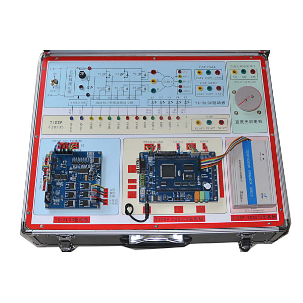


2) The DSP side uses the independently developed 28335 practical board development board, with the current m*nstream TMS320F28335 as the core, in the form of a six-layer core board + base board;
3) The BLDC motor platform adopts three-phase full-bridge isolation control and precise PID algorithm to ensure accurate motor operation;
4) The control signal of the DC motor driver board uses the sink current drive method, which supports direct drive of most microcontrollers ;
5) 42 stepper motor driver is an economical stepper motor driver with high stability, reliability and anti-interference performance. It is suitable for various industrial control environments and has automatic half-flow, low-voltage shutdown, overcurrent protection and overheating shutdown functions. ;
6) The onboard hardware resources are rich and the external expansion function is powerful, which can meet the needs of various project experiments;
7) 7.0-inch touch display adopts industrial grade to meet the harsh working environment, and the friendly human-machine interface facilitates your better operation;
8) The W5300 module supports software and hardware mixed TCP/IP protocols: TCP, UDP, ICMP, IGMP, IPv4, ARP, PPPoE, Ethernet; supports 8 independent ports (sockets) to be connected at the same time; network data transmission rate can reach 80Mbps ;Support ADSL connection (support PPPOE protocol, with PAP/CHAP authentication);
9) GPIO expansion function module includes 3x4 matrix keyboard, 12864LCD interface, 4-segment 8-bit digital tube, temperature and humidity sensor , infrared signal input interface, 8-channel LED, small DC motor and small stepper motor;
10) Adopt the split and independent modular design concept, which can not only demonstrate independently, but also work as a whole;
11) A uniquely designed motor control port for motor control;
12) Det*led user manual makes it easy for you to get started;
13) Focus on EMI design, stability and efficiency, including external expansion and all peripheral resources;
14) The m*nstream F28335 platform is the first choice in the field of motor control and power detection;
15) Rich experimental routines can meet various teaching experiments, especially in the field of motor control, making it convenient for users to transplant them.
3. System configuration
|
serial number |
project |
Require |
|
|
1 |
m*n processor |
TMS320F28335 C development board form) |
|
|
D S P end |
2 |
485 interface |
All the way 485 interface |
|
3 |
RS232 asynchronous serial port |
One RS232 interface jump selection, can carry out serial communication with the host computer, RS232 level |
|
|
4 |
CAN |
Used for CAN bus networking |
|
|
5 |
PWM interface |
12 channels of PWM (including 6 channels of enhanced PWM) |
|
|
6 |
ADC input interface |
16-channel AD input interface, feedback motor status |
|
|
7 |
audio port |
Audio interface, providing recording and broadcasting functions |
|
|
8 |
capture interface |
6-way CAP capture port (shared with the quadrature encoding pulse pin) |
|
|
9 |
DSP external expansion interface |
20-bit address lines and 16-bit data lines and others |
|
|
10 |
SD card interface |
User-provided SD card |
|
|
11 |
switching power supply |
+5V, 5A |
|
|
B L D C end |
12 |
Three-phase brushless motor interface |
Can be connected to 12V-36V motor, rated current does not exceed 4A |
|
13 |
Motor type |
Connecting brushless motors with and without position sensors |
|
|
14 |
26-pin interface, including PWM pulse input interface, AD interface |
Can be used with DSP-F28335A/B, DSP-F28335 basic connected, PWM input |
|
|
15 |
BLDC" ALL interface |
Hall sensor output for position sensor motor |
|
|
16 |
CAP_BEMF interface |
Connected to the control terminal CAP, the position sensorless motor back electromotive force output terminal |
|
|
17 |
CAP_HALL interface |
Connected to the control terminal CAP, there is a motor Hall output terminal with a position sensor. |
|
|
18 |
Motor power input interface |
24V DC bus voltage input terminal |
|
|
str*ght flow electricity machine end |
19 |
Two-phase DC motor interface x2 |
Can be connected to 7V-24v motor, rated current does not exceed 3A, anti-reverse connection |
|
20 |
Motor type |
Two-phase DC motor |
|
|
twenty one |
10-pin interface, including 3.3v-5. 0V control signal, 5V power supply |
The control signal can be connected by any microcontroller, and the signal input range is 3.3V-5.0V |
|
|
twenty two |
Motor power input interface |
24v DC power input terminal |
|
|
42 step Enter electricity machine end |
twenty three |
Two-phase stepper motor interface |
Drives 35, 39, 42, and 57 type 4, 6, and 8-wire two-phase hybrid stepper motors. There are 4 subdivisions, with a maximum of 16 subdivisions. |
|
twenty four |
Motor type |
Type 42 4-wire two-phase hybrid stepper motor |
|
|
25 |
6-pin interface, including control signals, power supply |
The 5V pulse signal is given by the microcontroller |
|
|
26 |
Motor power input interface |
24V DC power input terminal |
|
|
show Show end |
27 |
LCD |
Industrial-grade 7.0-inch LCD serial screen, 800*480 resolution, 5V power supply, with touch screen |
|
28 |
core processor |
CORTEX-M3 core + high-speed FPGA |
|
|
29 |
Communication Interface |
RS232 level |
|
|
30 |
PC software |
VisualTFT |
|
|
Outside DSP expand mold piece |
31 |
W5300 network port module |
Supports mixed software and hardware TCP/IP protocols: TCP, UDP, ICMP, IGMP, IPv4, ARP, PPPOE, Ethernet; supports 8 independent ports (sockets) simultaneous connection; network data transmission rate can reach 80Mbps; supports ADSL connection (supports PPPOE protocol, with PAP/CHAP authentication) |
|
32 |
GPIO expansion application module |
Including 3*4 matrix keyboard, 12864LCD interface, 4-segment 8-bit digital tube, temperature and humidity sensor, infrared signal input interface, 8-channel LED, small DC motor and small stepper motor |
4. DSP core system board parameters
4. DSP core system board parameters
1.DSP core board parameters
1) Processor: TMS320F28335, clock frequency 150MHz.
2) Low power consumption design, core voltage 1.9V, I/0 port voltage 3.3V.
3) On-chip: RAM 34KX16 bits, Flash 256KX16 bits.
4) External expansion: RAM 256KX16 bits, Flash 512KX16 bits.
5) Compatible with +3.3V and +5V power interfaces.
6) Minimum system version, 2*80-pin interface, convenient for secondary development.
7) Multi-interface design, suitable for motor control, power equipment control and industrial control, etc.
8) 18 channels of PWM, 6 channels of HRPWM (high precision), 2 channels of QEP, 6 channels of CAP,
9) 16-channel 12-bit ADC, 3-channel SCI, 2-channel MCBSP, 2-channel CAN,
10) 1 channel SPI, 1 channel I2C.
2•System backplane platform
1) JTAG interface: DSP emulator connection interface, which can perform online simulation and programming programs.
2) SCI interface: 1 channel 232 interface, 1 channel 485 interface, which can carry out serial communication with the host computer.
3) PWM interface: 18PWM (including 6 high-precision HPWM), convenient for motor control.
4) CAP interface: 4-way CAP capture port (shared with 6-way orthogonal encoding pulse pins).
5) CAN: 1 CAN2. 0 interface, used for CAN bus networking.
6) ADC input interface: 16-channel AD input interface, 12-bit accuracy, input voltage range: 0-3V.
7) Audio interface: 3-way Adui o interface, providing recording and broadcasting functions
8) Motor control interface: two sets of motor control interfaces, each group can control a 3-phase motor.
9) DSP external expansion interface: 20-bit address line and 16-bit data line and others.
10) An X1226 real-time clock and 2KB of I2C EEPROM.
11) Manual reset button to facilitate user reset operation
12) SD card slot: You can plug in a mobile SD card
3•Brushless motor driver board parameters
1) DC bus voltage +12~36V
2) The rated current of the motor does not exceed 4A
3) Power supply voltage of motor Hall sensor +5V
4) Overvoltage and overcurrent indication
4•DC motor driver board parameters
1) Support motor voltage 7-24V, anti-reverse connection
2) Dual-channel motor interface, each channel has a maximum load current of 3A, and each channel has an independent 3A over-current protection
3) The control signal of the L298N motor driver chip has the same logic. Each channel supports three-wire control enable, forward and reverse rotation and braking.
4) The enable signal can be connected to PWM externally, and the forward and reverse control signals can be connected in series to the limit switch.
5) The control signal uses a sink current drive method, which supports direct drive by most microcontrollers.
6) Use optocoupler to isolate all control signals
5•Stepper motor driver board
1) The TB6560 driver is powered by a DC power supply. The power supply voltage range is 8V DC-35V DC. It is recommended to use 24V DC for power supply. It is recommended to use 24V/5A switching power supply for power supply.
2) The TB6560 driver adopts a differential interface circuit which is suitable for differential signals, single-ended common cathode and common anode interfaces. It is isolated through high-speed optocoupler, allowing it to receive signals from long-line drivers, open collectors and PNP output circuits.
3) The driver is m*nly used to drive 35, 39, 42, and 57 type 4, 6, and 8-wire two-phase hybrid stepper motors. Its subdivisions are
4 types, up to 16 subdivisions
4) The driving current range is 0.3A-3A, the output current has 14 levels, the current resolution is about 0.2A, and it has automatic half-current, low-voltage shutdown, over-current protection and overheating stop function speed indication.
 Wechat scan code follow us

24-hour hotline+86 18916464525

Phone18916464525
ADD:Factory 414, District A, No. 6, Chongnan Road, Songjiang Science and Technology Park, Shanghai ICP: Sitemap