Shanghai Daiyu Education Equipment Manufacturing Co., Ltd.
Language:


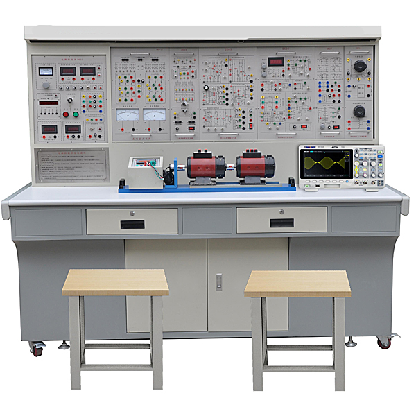


"ZRDDL-2 circuit analysis and power electronic technology experimental device" is a comprehensive experimental device launched by our company based on the summary of domestic electrical and electronic experimental equipment and using mature technology. It integrates the current undergraduate, junior college, technical secondary school and vocational colleges in China. It is developed to meet the requirements of the school's "Circuit Analysis", "Electrical Fundamentals", "Electrical Engineering", "Power Electronics Technology" and other course experimental syllabus. It is especially suitable for the upgrading of existing experimental equipment in colleges and universities, and technical secondary schools and vocational schools. When the laboratory is newly built or expanded , experimental courses can be quickly opened to provide ideal experimental equipment.
2. Characteristics
1. Strong comprehensiveness: It integrates all the practical tr*ning contents of the current basic electrical and electronic courses in various domestic schools.
2. Strong adaptability: The depth and breadth of the tr*ning can be flexibly adjusted according to needs. The device adopts a hanging box structure and is easy to replace. Adding components can expand functions or develop new tr*ning projects.
3. The measuring instrument has high precision and adopts digital and intelligent modes, which is in line with the development direction of modern measurement.
4. High safety performance: The 380V AC output on the tr*ning screen is equipped with an overcurrent protection device. If there is a direct short circuit or overload between phases or lines, and the current exceeds the set value, the system will alarm and cut off the m*n power supply to ensure the safety of the equipment.
5. The device has reasonable structure, superior performance, complete supporting facilities and luxurious appearance.
6. Depending on the voltage, the tr*ning cables and sockets adopt different structures, making them safe and reliable to use.
3. Technical performance:
1. Working power supply: three-phase four-wire (or three-phase five-wire) ~ 380V ±5% 50Hz
2. Temperature: -10℃~40℃, relative humidity <85% (25℃)
3. Device capacity: <1.5KVA
4. Weight: 200Kg
5. Overall dimensions: 1700mm×700mm×1600mm
4. Basic configuration and functions of the tr*ning device
This tr*ning platform is m*nly composed of a tr*ning screen, a tr*ning hanging box, a tr*ning table, etc.
(1) Power control panel
The tr*ning screen is an iron double-layer matt dense spray-p*nted structure with an aluminum panel. It provides AC power supply, DC regulated power supply, constant current source, function signal generator (including frequency meter), and test instruments for the tr*ning hanging box. and tr*ning devices, etc. The specific functions are as follows:
1. Provide three-phase 0~450V and single-phase 0~250V continuously adjustable AC power supply. The output of the adjustable AC power supply is equipped with over-current protection technology. Inter-phase, inter-line over-current and direct short circuit can be automatically protected. It is equipped with a pointer AC voltmeter. The three-phase grid voltage and three-phase voltage regulation can be indicated separately through the switch. The output voltage.
2. Provide two low-voltage regulated DC 0~30V/1A continuously adjustable power supplies, equipped with a digital voltmeter to indicate the output voltage, and the voltage is stable.
The stability is ≤0.3%, the current stability is ≤0.3%, and it is equipped with short-circuit soft cut-off protection and automatic recovery function.
3. Provide a continuously adjustable constant current source of 0~200mA, divided into three levels: 2mA, 20mA and 200mA, starting from 0mA, with an adjustment accuracy of 1‰.
The load stability is ≤5×10⁻⁴, the rated change rate is ≤5×10⁻⁴, it is equipped with a digital DC milliamp meter to indicate the output current, and has output open circuit and short circuit protection functions.
4. Provide a 220V, 30W fluorescent lamp for experimental bench lighting, and a 220V, 30W fluorescent lamp tube for experiment.
Lead out the four ends of the lamp filament for experimentation.
5. Provide a true effective value AC digital voltmeter with a measuring range of 0~500V, automatic range judgment and automatic switching, and an accuracy of 0.5
Level, three and a half digit display.
6 Power output function generator:
1) Use direct digital frequency synthesis (DDS) to generate high-precision sine waves, square waves and triangle waves. Use large-screen LCD to display output frequency, waveform, and attenuation value.
2) Sine wave output amplitude ≥10V, output impedance 50Ω, distortion <1% (0.1HZ-- 1KHz).
3) Frequency range: 0.1HZ~3MHz, use the keyboard to directly enter numbers to set the frequency.
4) The output amplitude is adjusted by a potentiometer, and the sine wave output has 20db and 40db attenuation.
5) Square wave duty cycle is adjustable, adjustment range: 1%-99% adjustment; square wave and triangle wave adopt TTL level output.
6) The frequency meter has a maximum measurement range of 100MHz and automatically shifts gears.
7. Instrument and controlled source function board
1. Digital display AC voltage, range 0~500V, 1 piece, with over-range protection, accuracy level 0.5
2. Digital display AC ammeter, range 0~5A, 1 piece, with over-range protection, accuracy level 0.5
3. Two DC digital display voltmeters, measuring range 0~300V, divided into three levels: 2V, 20V, 300V, direct key switch, three
Half-digit display, input impedance 10MΩ, accuracy level 0.5, and functions such as over-range alarm, indication and m*n power cutoff.
4. One DC digital display mA meter, measuring range 0~2000mA, divided into three levels: 20mA, 200mA, 2000mA, direct key switch
It has a three-and-a-half-digit display, an accuracy of 0.5, and has the functions of over-range alarm, indication, and cutting off the m*n power supply.
5. One digital display AC millivolt meter, measuring range 0~500V; accuracy level 0.5, with over-range protection.
8. Smoothing reactor: 100mH, 200mH, 700mH inductance, m*nt*ning linearity at 1A.
9. A set of three-phase synchronous transformers
10. Other facilities: Two square st*nless steel tubes can be used to hang experimental components. There are 7-core, 3-core and other sockets at the bottom of the groove. The power supply of the pendant is provided by these sockets. There are single-phase three-pole 220V power sockets and three-phase four-pole 380V power sockets on both sides of the control panel.
DK02 Experimental Table: Iron double-layer matt dense textured spray-coated structure, the desktop is made of wear-resistant high-density board; there are two large drawers (with locks) on the left and right, respectively for placing tools and materials.
(2) Experimental components
1. ZRDG-03 circuit basic experiment box
Provides Kirchhoff's law (three typical fault points can be set), superposition principle (three typical fault points can be set), Thevenin's theorem, Norton's theorem, two-port network, reciprocity theorem, R, L, C series resonant circuit , R, C series and parallel frequency selection network and first-order and second-order dynamic circuit experiments. All experimental devices are complete, the experimental units are clearly isolated, the experimental circuits are complete and clear, and the verification experiments and design experiments are combined.
2. ZRDG-04 AC circuit experiment
Provides experiments on single-phase and three-phase load circuits, fluorescent lamps, transformers, mutual inductors and watt-hour meters. The loads are three completely independent lamp groups, which can be connected into Y or △ three-phase load lines. Each lamp group is equipped with three parallel incandescent screw sockets (each group is equipped with three switches to control three loads). On/off of the parallel branch), nine incandescent lamps below 60W can be inserted. Each lamp group is equipped with a current socket to facilitate current testing; each lamp group is equipped with an overvoltage protection circuit to ensure the safety of experimental students and prevent the lamp group from Damage due to overvoltage; fluorescent lamp experimental devices include 30W ballast, high-voltage capacitor (0.47µF/500V, 4.7µF/500V), starter and short-circuit button; one iron core transformer (50VA, 36V/220V) , both the primary and secondary sides are equipped with fuses and current sockets to facilitate current testing;
3.ZRDG-05 component box
There are three sets of high-voltage capacitors (one for each set of 1µF/500V, 2.2µF/500V, and 4.7µF/500V high-voltage capacitors) for experiments on changing the power factor; various components required for experiments are provided, such as resistors, diodes, Luminous tubes, voltage regulator tubes, potentiometers and 12V light bulbs, etc. are also provided with decimal adjustable resistance boxes with resistance values from 0 to 99999.9Ω/2W.
4.ZRDG-06. Single-phase intelligent power and power factor meter
Use dedicated DSP to calculate active power and reactive power. The power measurement accuracy is 0.5, and the voltage and current ranges are 450V and 5A respectively. It can measure the active power, reactive power, power factor and load properties of the load; in addition, it can also store and record 15 sets of power and power factor tests. The result data can be queried group by group.
5.DQ27 three-phase adjustable resistor
Three groups of 900Ω×2/0.41A are used as adjustable resistive loads in experiments.
6.DK03 thyristor m*n circuit
Provides 6 5A/1000V thyristors. Each thyristor is equipped with over-current and over-voltage protection devices. The thyristors can be triggered by external signals (with a trigger pulse input interface), which can better complete design experiments; equipped with Precision pointer type DC voltmeter with mirror ±300V, accuracy level 1.0, DC ammeter with mirror ±2A, one accuracy level 1.0 each.
7.DK04 three-phase thyristor trigger circuit
Provide three-phase trigger circuit, power amplifier circuit, etc., used in conjunction with the "thyristor m*n circuit".
8.DK05 thyristor trigger circuit experiment
Provides five trigger circuit experiments including single-junction transistor trigger circuit, sine wave synchronous phase-shift trigger circuit, sawtooth wave synchronous phase-shift trigger circuit, single-phase AC voltage regulation trigger circuit, and TCA785 integrated trigger circuit.
9.DK08 given and experimental devices
Provides a given (±15V adjustable voltage output), varistor (as an overvoltage protection component, internally connected in a delta connection), and a diode.
10. DK09 new device characteristics experiment
We provide SCR, MOSFET, IGBT, GTO, and GTR power electronic devices, which can be used together with other components to measure their characteristic curves.
11.DK11 single-phase voltage regulation and adjustable load
Provides a 0~250V/0.5kVA single-phase AC auto-voltage regulator to provide adjustable power supply for corresponding experiments; a rectifier filter circuit and 0~180Ω/1.3A (series) or 0~45Ω/2.6A ( Parallel) porcel*n plate adjustable resistor to provide an adjustable resistive load for the corresponding experiment.
12.DK12 three-phase core transformer
Provide a three-phase core transformer (the transformer has 2 sets of secondary windings, the voltage of the primary and secondary windings is 127V/63.6V/31.8V), used for asynchronous motor cascade speed regulation experiments and three-phase bridge, single Phase bridge active inverter circuit experiment; there is also a three-phase uncontrollable rectifier circuit to generate DC power.
13.DK14 single-phase AC and DC frequency conversion principle
It is used to demonstrate the principle of AC-AC frequency conversion. It m*nly allows students to understand the formation method of SPWM sine wave pulse width modulation signal, understand the characteristics and use of IGBT tube-specific integrated driver chips, and be able to complete the following experimental projects: (1) The process of SPWM wave formation ; (2) The working conditions and waveforms of the AC-AC frequency conversion circuit under different loads (resistance-inductance load), and study the impact of operating frequency on the circuit operating waveform; (3) The operating characteristics of the IGBT tube dedicated integrated driver chip.
14.DK17 DC/DC conversion circuit
Provides the m*n circuit and control circuit for the DC/DC conversion circuit experiment. The power electronic device is IGBT, the control circuit uses PWM control integrated circuit SG3525, and the required observation holes are also provided on the panel of the hanging box.
15.DK07 DC chopper experiment
Provide the components required to form a DC chopper circuit and use a dedicated PWM control integrated circuit SG3525. Can complete the buck chopper circuit (Buck Chopper), boost chopper circuit (Boost Chopper), boost-buck chopper circuit (Boost-Buck Chopper), Cuk chopper circuit, Sepic chopper circuit, and Zeta chopper in the textbook Six typical experiments on circuits.
16. The DK22 single-phase AC voltage regulation/power regulation circuit
is designed based on the relevant content in "Power Electronics Technology" (Fourth Edition) edited by Professor Wang Zhaoan and Professor Huang Jun of Xi'an Jiaotong University to realize single-phase AC voltage regulation and AC power regulation. experimental content. The power electronic device used is a bidirectional thyristor. In the AC voltage regulation experiment, the trigger control circuit is composed of a bidirectional trigger diode; in the AC power regulation experiment, the trigger control circuit is composed of a 555 time base circuit.
17. ZR07 experimental connection line:
According to the characteristics of different experimental projects, two different experimental connection lines are equipped. The high-power part adopts a high-reliability sheathed structure pistol plug connection line (there is no possibility of electric shock), and the inside is made of oxygen-free copper to make it look like h*r. The thin multi-stranded wire is ultra-soft and covered with a nitrile polyvinyl chloride insulation layer, which has the advantages of softness, high voltage resistance, high strength, anti-hardening, and good toughness. The plug is made of solid copper and is coated with beryllium light copper shrapnel. , the contact is safe and reliable; the weak current part adopts elastic beryllium light copper exposed structure connecting wire. Both wires can only match the sockets with corresponding inner holes, which greatly improves the safety and rationality of the experiment.
18. Teaching software
1. Electrical safety and electric shock first *d simulation teaching software
The software uses a combination of two-dimensional and three-dimensional virtual images to teach students the safety and first *d methods of using electricity. The software includes single-phase electric shock, two-phase electric shock, step electric shock, low-voltage electric shock first *d, high-voltage electric shock first *d, artificial respiration first *d, Principles of hand-holding breathing rescue method, chest cardiac compression and other protective methods are expl*ned and taught. Principles of single-phase electric shock are divided into rep*ring live disconnection, rep*ring socket electric shock, and outdoor electric shock. The teaching of low-voltage electric shock and high-voltage electric shock m*nly expl*ns and demonstrates to students how to rescue people who are suffering from low-voltage electric shock or high-voltage electric shock. Artificial respiration rescue method, hand-holding breathing rescue method, and chest cardiac compression rescue method are demonstrated using 3D virtual simulation technology. After rendering and Polish it to make the model look like the real part and look realistic. Through practical tr*ning, students can be educated on the safe use of electricity in the tr*ning room, improve students' safety awareness, and enable students to learn some self-rescue methods, so that students can take cert*n safety measures to protect themselves when encountering danger, and become familiar with various Causes of electrical accidents and practical measures to deal with them to reduce the occurrence of electrical accidents.
2. M*ntenance of electricians , electronic motors and vocational qualification tr*ning assessment simulation software
This software is in apk format and can be used on PC or mobile. This software can set faults manually or automatically. This software can manually set fault points through the green box in the circuit diagram (you can set up to 39 fault points), you can also automatically set one random fault point, two random fault points, three random fault points, four random fault points, and five random fault points through the system. It has functions such as toolbox, component library, magnifying glass, circuit diagram, etc. You can choose a multimeter for testing through the toolbox, select appropriate components through the component library, and clearly understand each component and circuit through the magnifying glass. This software allows students to understand the working principle and circuit structure of the motor star-delta start control circuit through the setting of faults in the motor star-delta start control circuit and various investigations.
3. Virtual spectrum analyzer, logic analyzer, oscilloscope, and three-meter simulation software:
This software is in apk format and can be used on PC or mobile terminals. The functions of this software are: resistance measurement, AC voltage measurement (measuring transformer, if the multimeter burns out when measuring the transformer, black smoke will emit prompts and can reset the multimeter), determine the polarity of the transistor, measure the DC voltage (the light turns on when the ammeter is turned on), measure the DC current, and determine the quality of the capacitor. This software can drag the red and black pen tips at will. When the two pen tips are dragged and positioned on the object to be measured, a red circle will be displayed. If the positioning is not accurate, no red circle will be displayed, and when incorrect operations are performed (such as the wrong range selected, If the measured data is wrong, etc.), the meter pointer will be unresponsive, prompting errors and re-measurement, etc. This multimeter can select AC voltage range, DC voltage range, resistance range, current range, resistance adjustment to 0, and can enlarge the display data. Clearly view the measured data size. Students can learn the correct use of multimeters through this software.
4. Microcontroller and plc programmable design and control virtual simulation software:
This software is developed based on unity3d and has built-in experimental steps, experimental instructions, circuit diagrams, component lists, connection lines, power on, circuit diagrams, scene reset, return and other buttons. After the connections and codes are correct, you can start/stop, The forward movement and reverse movement buttons operate the 3D machine tool model to move. In the connected line state, the 3D machine tool model can be enlarged/reduced and translated.
1. Relay control: Read the experiment instructions and enter the experiment. By reading the circuit diagram, select the relays, thermal relays, switches and other components in the component list and drag and drop them into the electrical cabinet. The limiters are placed in the three-dimensional On the machine tool model, you can choose to cover it, and some component names can be renamed. Then click the Connect Line button to connect terminals to terminals. After successfully connecting the machine tool circuit, choose to turn on the power and proceed. If the component or line An error box will pop up if there is a connection error, and the scene can be reset at any time.
2. PLC control: The experiment is the same as relay control, with the addition of PLC control function. After the connection is completed, enter the program writing interface through the PLC coding button, and write two programs, forward and reverse, with a total of 12 ladder diagram symbols. The writing is completed. Finally, select Submit for program verification. After the verification is successful, turn on the power for operation. Error boxes will pop up for component, line connection, and code errors, and the scene can be reset at any time.
3. Single-chip microcomputer control: The experiment is the same as relay control, with the addition of single-chip microcomputer control function. After the connection is completed, enter the programming interface through the C coding button, enter the correct C language code, and after successful submission and verification, turn on the power for operation, components, lines If there are connection or code errors, an error box will pop up, and the scene can be reset at any time.
6. Experimental projects
1. 1) Circuit analysis experiment
2. Use of basic electrical instruments and calculation of measurement errors
3. Methods to reduce instrument measurement errors
4. Surveying and mapping of volt-ampere characteristics of linear and nonlinear circuit components
5. Measurement of potential and voltage and drawing of circuit potential diagram
6. Kirchhoff’s law verification and fault diagnosis
7. Superposition theorem verification and fault judgment
8. Equivalent transformation of voltage source and current source
9. Verification of Thevenin’s theorem
10. Verification of Norton’s Theorem
11. Dual-port network test
12. Verification of reciprocity theorem
13. Experimental research on controlled sources
14. Test of RC first-order circuit response
15. Study of second-order dynamic circuit response
16. Testing of impedance characteristics of R, L and C components
17. RC series and parallel frequency selection network characteristics test
18. Research on R, L, C series resonant circuit and use three-meter method to measure equivalent parameters of AC circuit
19. Research on phasors of sinusoidal steady-state AC circuit (experiment on improving the power factor of fluorescent lamps)
20. Mutual induction experiment
21. Testing of single-phase core transformer characteristics
22. Measurement of voltage and current of three-phase AC circuit
23. Measurement of power factor and phase sequence
(2) Power electronics technology experiments
24. Unijunction transistor trigger circuit
25. Sine wave synchronous phase-shift trigger circuit experiment
26. Sawtooth wave synchronous phase-shift trigger circuit experiment
27. Siemens TCA785 integrated trigger circuit experiment
28. Single-phase half-wave controlled rectifier circuit experiment
29. Single-phase bridge semi-controlled rectifier circuit experiment
30. Single-phase bridge type fully controlled rectifier and active inverter circuit experiment
31. Three-phase half-wave controllable rectifier circuit experiment
32. Three-phase bridge semi-controlled rectifier circuit experiment
33. Three-phase half-wave active inverter circuit experiment
34. Three-phase bridge type fully controlled rectifier and active inverter circuit experiment
35. Single-phase AC voltage regulating circuit experiment
36. Single-phase AC power regulation circuit experiment
37. Three-phase AC voltage regulating circuit experiment
38. Characteristics experiment of unidirectional thyristor (SCR)
39. Experiment on characteristics of turn-off thyristor (GTO)
40. Power field effect transistor (MOSFET) characteristics experiment
41. Power Transistor (GTR) Characteristics Experiment
42. Insulated Bipolar Transistor (IGBT) Characteristics Experiment
43. Single-phase sine wave pulse width modulation (SPWM) inverter circuit experiment (IGBT)
44. DC/DC conversion circuit experiment (IGBT)
45. Performance research on DC chopper circuits (six typical circuits: buck chopper circuit, boost chopper circuit, buck-boost chopper circuit, Cuk chopper circuit, Sepic chopper circuit, and Zeta chopper circuit) (IGBT )
7. Configuration list
|
serial number |
serial number |
Name |
quantity |
Remark |
|
1 |
DLDZ-1 |
Power control panel |
1 set |
|
|
2 |
DK02 |
Experiment table |
1 piece |
|
|
3 |
DK03 |
Thyristor m*n circuit |
1 item |
|
|
4 |
DK04 |
Three-phase thyristor trigger circuit |
1 item |
|
|
5 |
DK05 |
Thyristor trigger circuit experiment |
1 item |
|
|
6 |
DQ27 |
Three-phase adjustable resistor |
1 item |
|
|
7 |
ZRDG-03 |
Circuit basic experiment box |
1 item |
|
|
8 |
ZRDG-04 |
AC circuit experiment |
1 item |
|
|
9 |
ZRDG-05 |
Component box |
1 item |
|
|
10 |
ZRDG-06 |
Single-phase intelligent power and power factor meter |
1 item |
|
|
11 |
ZRDG-09 |
True rms AC digital millivolts |
1 item |
|
|
12 |
ZRDG-10 |
Controlled source (four channels), gyrator, negative impedance converter |
1 item |
|
|
13 |
DK22 |
Single-phase AC voltage regulation/power regulation circuit |
1 item |
|
|
14 |
DK08 |
Given and experimental devices |
1 item |
|
|
15 |
DK09 |
New device characteristics experiment |
1 item |
|
|
16 |
DK11 |
Single-phase voltage regulation and adjustable load |
1 item |
|
|
17 |
DK12 |
Three-phase core transformer |
1 item |
|
|
18 |
DK14 |
Single-phase AC and DC frequency conversion principle |
1 item |
|
|
19 |
DK07 |
DC chopper experiment |
1 item |
|
|
20 |
DK17 |
DC/DC conversion circuit |
1 set |
|
|
twenty one |
ZR07 |
Highly reliable sheath structure pistol plug experimental connection cable and accessories |
1 set |
 Wechat scan code follow us

24-hour hotline+86 18916464525

Phone18916464525
ADD:Factory 414, District A, No. 6, Chongnan Road, Songjiang Science and Technology Park, Shanghai ICP: Sitemap