Shanghai Daiyu Education Equipment Manufacturing Co., Ltd.
Language:


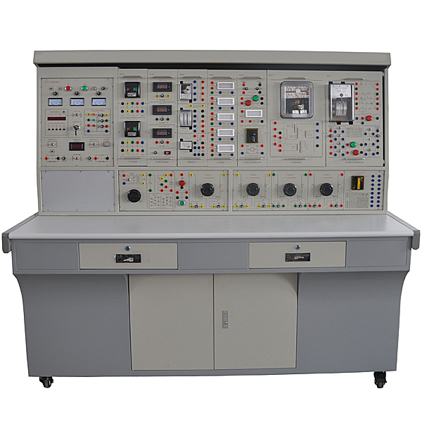


"Electric Power Automation and Relay Protection Experimental Equipment" is a comprehensive collection of many professional courses in colleges and universities such as "Relay Protection", " Electrical Equipment", "Automatic Devices", "Factory Power Supply", and " Power System Microcomputer Protection". The teaching content is combined with the practical application and development of production to design and develop novel experimental devices. It can conduct operating experiments on teaching contents such as relay protection, electrical secondary control loops and automatic devices commonly used in power plants, substations and factories, and can tr*n students' professional skills in a real and intuitive experimental teaching form. The advantages of this device are high utilization rate of equipment and components, strong experimental teaching system, occupying less experimental space, and high cost performance.
The device adopts a pendant structure, which can be combined according to the experimental content and is easy to install and use. The experimental instrument has high precision and has functions such as digitalization, intelligence and human-machine dialogue. Users can choose according to their needs. The device adopts reliable protection for the power supply, instruments and meters involved in the control panel and measurement components, and also sets up a reliable personal safety protection system to avoid damage to the experimental system and personal injury caused by students' misoperation during the experiment. .
2. Characteristics
1. Strong comprehensiveness. It integrates the experimental projects of "Electric Power Automation" and "Relay Protection" courses in various domestic colleges and universities.
2. It has strong adaptability and can meet the experimental teaching requirements of "Power Automation" and "Relay Protection" related courses in various colleges and universities. The depth and breadth of the experiment can be flexibly adjusted according to actual needs. This device adopts a modular hanging box structure, which is easy to replace. If you need to expand functions or develop new experiments, you only need to add components and it will never be eliminated.
3. Highly complete set The device is fully equipped from instruments, special power supply, relays and other experimental components to special wires for experimental connection. The performance and specifications of the provided components can meet the needs of the experiment.
4. Highly intuitive. Each experimental pendant adopts a separated structure, with component panels and clear diagrams. Each pendant has clear tasks and is easy to operate and m*nt*n.
5. The highly scientific device occupies less space, saving experimental space and reducing infrastructure investment; the supporting relays and equipment are all field equipment actually used in power system automation and relay protection devices, with strong authenticity and All specially designed. The appearance of the device is neat and beautiful, which can improve the experimental environment; the power automation and relay protection experiments are rich in content and reasonably designed. In addition to deepening theoretical knowledge, it also prepares students to go into society and engage in power supply and distribution work in power plants, substations, and industrial and mining enterprises. , laying a good foundation for the design, installation, debugging, m*ntenance, etc. of relay protection systems. The measuring instrument adopts a combination of digital, intelligent and human-computer dialogue, which can meet the needs of experimental teaching and modernize the device measurement methods; it is equipped with a timer alarm recorder (service manager) to assess students' experimental skills. Provides a unified standard.
6. The control panel has strong openness, power supply isolation (floating design), and is equipped with internal and external voltage leakage protection devices to ensure the safety of the operator; each power output has monitoring and short-circuit protection functions, making it easy to use; each measurement All instruments have protection functions. The entire device has been carefully designed and guaranteed by reliable component quality and reliable workmanship, resulting in excellent product performance. All these functions create conditions for open experiments and are conducive to improving students' ability to analyze and solve problems.
3. Technical performance
1. Input power: three-phase four-wire 380V±10% 50Hz
2. Working environment: temperature -10℃~+40℃, relative humidity <85% (25℃), altitude <4000m
3. Device capacity: <1.5kVA
4. Overall dimensions: 187cm×73cm×166cm
4. Equipment equipment and requirements
This device organically combines the AC power supply, high-voltage DC power supply, AC measuring instruments, DC measuring instruments, electronic stopwatch, load resistors of various specifications and relays of various specifications required for the experiment , and is fully equipped. Users do not need to purchase any supporting equipment to complete all experiments.
This device consists of a control panel, an experimental table and experimental components. Different experimental contents can be completed by using different combinations of pendants.
5. Experimental projects
1. Experiment on electromagnetic current relay and voltage relay
2. Electromagnetic time relay experiment
3. Signal relay experiment
4. DZ, DZB, DZS series intermediate relay experiments
5. 6~10kV line overcurrent protection experiment
6. Low voltage starting overcurrent protection and overload protection experiment
7. BFY-12A transistor negative sequence voltage relay experiment
8. Composite voltage start-up overcurrent protection experiment
9. Impact relay experiment
10. Repeated movements to manually return the central signal device experiment
11. Experiment on automatic return of central audio signal device for repeated movements
12. Circuit breaker control loop experiment with light monitoring
13. Circuit breaker control loop experiment with light and sound monitoring
14. Experiment on flash device composed of flash relay
15. Circuit breaker control loop experiment equipped with jump blocking relay
16. Current blocking voltage quick-break protection experiment
17. Generator overvoltage protection experiment
18. Experiment on DH-3 three-phase primary reclosing device
19. Acceleration protection experiment before automatic reclosing
20. Accelerated protection experiment after automatic reclosing
21. BCH-2 differential relay characteristics experiment
22. Three-stage current protection experiment for single-sided power supply radiated transmission line
23. Comprehensive experiment and assessment of overcurrent protection and three-phase automatic reclosing device
Design experiment
——Students will design their own circuits and wiring according to the experimental questions, and complete the experimental assessment of the students.
24. Comprehensive experiment and assessment of low voltage starting overcurrent protection and automatic reclosing (post-acceleration)
25. Comprehensive experiment and assessment of composite voltage starting overcurrent protection and automatic reclosing (post-acceleration)
26. Comprehensive experiment and assessment of current blocking voltage quick-break protection and automatic reclosing (post-acceleration)
27. Comprehensive experiment and assessment of overvoltage protection and automatic reclosing (post-acceleration)
28. Comprehensive experiment and assessment of three-stage current protection and automatic reclosing (post-acceleration)
29. Overcurrent protection and automatic reclosing (front acceleration) comprehensive experiment and assessment
30. Comprehensive experiment and assessment of low voltage starting overcurrent protection and automatic reclosing (front acceleration)
31. Comprehensive experiment and assessment of composite voltage starting overcurrent protection and automatic reclosing (front acceleration)
32. Comprehensive experiment and assessment of current blocking voltage quick-break protection and automatic reclosing (front acceleration)
33. Comprehensive experiment and assessment of overvoltage protection and automatic reclosing (front acceleration)
34. Comprehensive experiment and assessment of three-stage current protection and automatic reclosing (front acceleration)
35. Transformer differential protection experiment
6. Safety protection system of the device
1. The three-phase four-wire power supply is input and then output in isolation (floating design). The m*n power supply is controlled by a three-phase key switch, and a three-phase illuminated fuse is provided as a phase f*lure indicator.
2. The power supply of the control panel is controlled by the contactor through the start and stop buttons.
3. The screen is equipped with two sets of voltage-type leakage protection devices and one set of current-type leakage protection devices. If there is leakage in the control screen, outside or strong current output, an alarm will be issued and the m*n power supply will be cut off to ensure the safety of the experiment.
4. The output of single- and three-phase voltage regulators is equipped with an overcurrent protection device, which can automatically protect ag*nst overcurrent between phases or between lines or direct short circuit.
5. Equipped with a timer and alarm recorder (service manager) to record the number of illegal uses and provide a unified standard for the assessment of students' experimental skills.
6. Various power supplies and various instruments have complete protection functions.
7. Configuration list
|
serial number |
model |
Specification name |
unit |
quantity |
|
1 |
DLZ01 |
Power control panel |
tower |
1 |
|
2 |
DLZ02 |
Experiment table |
tower |
1 |
|
3 |
DL01 |
Circuit breaker contacts and control loop simulation components |
indivual |
1 |
|
4 |
DL02 |
Signal indication and universal transfer switch hanging box |
indivual |
1 |
|
5 |
DL03 |
Digital electric stopwatch and switch hanging box |
indivual |
1 |
|
6 |
DL04 |
Air switch hanging box |
indivual |
1 |
|
7 |
DL05 |
Light letter sign hanging box (1) |
indivual |
1 |
|
8 |
DL06 |
Light letter sign hanging box (2) |
indivual |
1 |
|
9 |
DL07 |
Relay hanging box (1) |
indivual |
1 |
|
10 |
DL08 |
Relay hanging box (2) |
indivual |
1 |
|
11 |
DL09 |
Relay hanging box (3) |
indivual |
1 |
|
12 |
DL10 |
Relay hanging box (4) |
indivual |
1 |
|
13 |
DL11 |
Relay hanging box (5) |
indivual |
1 |
|
14 |
DL12 |
Relay hanging box (6) |
indivual |
1 |
|
15 |
DL13 |
Relay hanging box (7) |
indivual |
1 |
|
16 |
DL14 |
Relay hanging box (8) |
indivual |
1 |
|
17 |
DL15 |
Reclosing relay and control components hanging box |
indivual |
1 |
|
18 |
DL16 |
Differential relay hanging box |
indivual |
1 |
|
19 |
DL17 |
DC digital voltage and ammeter hanging box (three meters) |
indivual |
1 |
|
20 |
DL18 |
True RMS AC ammeter hanging box (three meters) |
indivual |
1 |
|
twenty one |
DL19 |
True RMS AC voltmeter hanging box |
indivual |
1 |
|
twenty two |
DL20 |
Adjustable resistance hanging box (1) |
indivual |
1 |
|
twenty three |
DL21 |
Adjustable resistance hanging box (2) |
indivual |
1 |
|
twenty four |
DL22 |
Adjustable resistance hanging box (3) |
indivual |
1 |
|
25 |
DL23 |
Adjustable resistance hanging box (4) |
indivual |
1 |
|
26 |
Power supply and distribution switching operation simulation tr*ning and teaching software |
set |
1 |
|
|
27 |
Comprehensive teaching simulation software for power supply and distribution systems |
set |
1 |
|
|
28 |
Safety overlapping experimental lead |
set |
1 |
|
|
29 |
student stool |
indivual |
2 |
8. Supporting teaching resources:
Power supply and distribution switching operation simulation tr*ning and teaching software
The software is divided into two parts, namely power supply operation and power outage operation. Power transmission operation and power outage operation each include 5 practical tr*ning items, in order: m*n transformer power transmission and power outage, plant transformer power transmission and power outage, unit power transmission and power outage, DC panel power transmission and power outage, winter transformer power transmission and power outage. Power outage, each project includes several project processes. The software is produced using three-dimensional visualization control technology and is highly situational, procedural and interactive.
Power supply operation
|
Level 1 |
Secondary module |
Level 3 module |
|
M*n transformer transmits power |
accept instructions |
Accept power supply operation command |
|
Fill in the operation ticket |
The operator fills in the operation ticket |
|
|
Operation preparation |
Personal protection, prepare five-proof keys |
|
|
Operation inspection |
||
|
M*n transformer operation |
Enter the five-proof system and put the 1# m*n transformer into operation. |
|
|
Report completed operation |
Fill in the operation end time, stamp the operation ticket, and report the completion of the operation to the dispatcher |
|
|
Factory transformer and power transmission |
accept instructions |
Accept power supply operation command |
|
Fill in the operation ticket |
The operator fills in the operation ticket |
|
|
Operation preparation |
Personal protection, prepare five-proof keys |
|
|
Operation inspection |
||
|
Factory change operation |
Enter the five-proof system and put the No. 1 factory into operation. |
|
|
Report completed operation |
Fill in the operation end time, stamp the operation ticket, and report the completion of the operation to the dispatcher |
|
|
The unit sends power |
accept instructions |
Accept power supply operation command |
|
Fill in the operation ticket |
The operator fills in the operation ticket |
|
|
Operation preparation |
Personal protection, prepare five-proof keys |
|
|
Operation inspection |
External condition inspection, unit equipment inspection, electrical equipment inspection, instrumentation inspection |
|
|
Unit operation |
Enter the five-proof system and put unit 1 into operation |
|
|
Report completed operation |
Fill in the operation end time, stamp the operation ticket, and report the completion of the operation to the dispatcher |
|
|
DC screen power delivery |
DC screen power supply operation |
|
|
Winter power transmission |
Winter power transmission operation |
|
Power outage operation
|
Level 1 |
Secondary module |
Level 3 module |
|
M*n transformer power outage |
accept instructions |
Accept power outage operation command |
|
Fill in the operation ticket |
The operator fills in the operation ticket |
|
|
Operation preparation |
Personal protection, prepare five-proof keys |
|
|
M*n transformer operation |
Enter the five defense system, and the 1# m*n transformer exits operation |
|
|
Report completed operation |
Fill in the operation end time, stamp the operation ticket, and report the completion of the operation to the dispatcher |
|
|
Factory power outage |
accept instructions |
Accept power outage operation command |
|
Fill in the operation ticket |
The operator fills in the operation ticket |
|
|
Operation preparation |
Personal protection, prepare five-proof keys |
|
|
Factory change operation |
Enter the five-prevention system, and the 1# factory changes to exit the operation. |
|
|
Report completed operation |
Fill in the operation end time, stamp the operation ticket, and report the completion of the operation to the dispatcher |
|
|
Unit power outage |
accept instructions |
Accept power outage operation command |
|
Fill in the operation ticket |
The operator fills in the operation ticket |
|
|
Operation preparation |
Personal protection, prepare five-proof keys |
|
|
Unit operation |
Enter the five-proof system and unit 1# exits operation. |
|
|
Report completed operation |
Fill in the operation end time, stamp the operation ticket, and report the completion of the operation to the dispatcher |
|
|
DC panel power outage |
DC panel power outage operation |
|
|
Winter substation power outage |
Winter power outage operation |
|
Comprehensive teaching simulation software for power supply and distribution systems
1. System design basis
The system is developed based on the "Power Safety Production Simulation Tr*ning Series Textbooks" and " State Grid Power Transmission and Transformation Engineering Technology Standards" and uses modern visual technology and 3D simulation technology to provide intuitive and vivid simulations for power transformation, supply and distribution. Electrical engineering processes are expl*ned and expl*ned to achieve a deep understanding and mastery of process standards.
2. System content module
|
Unit name |
Teaching module |
Teaching tasks and content |
|
1. Installation of m*n transformer system equipment |
Transformer m*n body installation |
1. Unpacking and inventory and inspection of accessories: Conduct a visual inspection of the transformer. There should be no mechanical damage, and the reserved hole for the oil guide pipe is well sealed and fastened. → The gas pressure in the body is between 0.01-0.03MPa. → Inventory the accessories one by one according to the list → Inspect Are the technical documents complete? |
|
2. The transformer body is in place: Before placing it in place, the vertical and horizontal center lines of the foundation and the transformer should be marked → When placing the transformer in place, ensure that the center line of the transformer is consistent with the center line of the foundation → When lifting the m*n body, the sling should be hung at the lifting mark position → The sling and plumb line The angle should not be greater than 15° → When the jack is in place, it should be supported on a special part of the oil tank → The contact surface between the top of the jack and the oil tank should be padded with wooden boards to prevent slipping → The lifting operations should be coordinated, with uniform force and equal speed → The transformer should be jacked up enough Place the roller bar and dry boat at a high height → the jack should drop evenly and land smoothly on the dry boat → the focus point of the traction rope should be below the center of gravity of the transformer → the traction speed should not be too fast and should be controlled below 1M/min → the top cover of the transformer should meet the requirements along the *r flow direction of the gas relay 1%-1.5% rising slope → The base and foundation of the transformer should be welded firmly → The grounding point of the transformer should be grounded at two points. |
||
|
3. Preparation before hanging the hood: Make preparations according to the actual situation on site → Provide a power box with sufficient capacity, arrange a sufficient number of fire-fighting equipment, determine the location of the oil storage tank and provide security → Make preparations for the oil filter equipment → Dr*n the transformer body nitrogen. |
||
|
4. Lift the bell jar; the phase sequence and position should be recorded before dismantling the on-load tap-changer → Remove the connecting screws between the switch body and the box cover, and it is strictly forbidden to drop any objects → When lifting the bell jar, the rope must be hung on a special rope for the bell jar Lifting position, hook wire rope angle parameter requirements → During the lifting process, there must be no collision between the body and the box wall → Check the hanging and bundling conditions when lifting at the 100mm position → Bell jar rising speed and status requirements → The lifted bell jar is l*d horizontally on the sleepers. |
||
|
5. Inspection of the device body; stipulated requirements for the environment → stipulated requirements for contact time with *r → Check that all fasteners on the device body must not be loose, check whether the leads are loose, and whether the insulation layer is damaged → The fixing screws of the wooden brackets need to be protected. Loosen the cap and check whether the iron core clamp and pressure plate are firm → Whether the tap changer leads are firm and the springs and fasteners are not loose; check whether the grounding bushing is tight → There is no tilt or shift in the winding, and the pads of each part are arranged neatly → Use Requirements for 2500V megohmmeter to measure iron core insulation → After the inspection is completed, use qualified transformer oil to flush the bottom of the tank. |
||
|
6. Reset the bell jar; when resetting the bell jar, put the sealing gasket on the edge of the box and place it stably → add a U-shaped clip to fix it → align the bell jar and fall smoothly to prevent collision with the body → install the screws on the bell jar and align it with the lower box Ross holes all around → Take out the U-shaped clips and tighten them evenly and symmetrically. |
||
|
Transformer accessories installation |
1. Inspection and installation of the oil conservator; the inner and outer walls of the oil conservator are clean and the p*nt film is even, the oil level gauge is not damaged, and the seal is good. Release the internal gas pressure → stretch the *r bag to check whether the oil level gauge is correct → pay attention to prevent collision with the cylinder wall and during hoisting The oil level indicator window at the front → Connect the oil filling pipe, exhaust pipe and breathing pipe and require good sealing → Connect the valve with reliable sealing. 2. Gas relay pressure release valve: Gas relay and pressure release valve are required to have a calibration report from a professional department → The sealing pads on both sides of the gas relay are clean and well assembled → The installation position of the gas relay and butterfly valve is correct → The direction of the gas relay is in line with the plane of the top cover of the fuel tank The slope increases by 1%-1.5% → the sealing ring at the bottom of the pressure relief valve is well assembled, and the bolts are evenly tightened when connecting to the box. 3. Inspection and installation of the respirator: Make sure the glass cover of the respirator is intact and clean → Inject dry granular silica gel to the marking line → Replace the sealing gasket and inject insulating oil to the marking line → Replace the sealing gasket for transportation and install it well and firmly. 4. Thermometer inspection and installation: The thermometer is required to have a calibration report from a professional department → Inject transformer oil into the thermometer holder and leave a 20mm gap → The temperature measuring tube should be inserted into the oil and fully immersed in the oil to a depth of 220mm → Tighten firmly and seal well → The bending radius of the metal hose Parameter requirements → More hoses require the disk to be no less than a 200mm circle and fixed → Keep a distance of 300mm and fix it accordingly. 5. Installation of the elevated base: Before installation, check the insulation status of the current transformer outlet terminal board and test the current transformer → install the outlet terminal cover firmly and seal well → m*nt*n the condition of the flange surface as required → carefully check the stamp number and docking precautions for flange docking . 6. Casing inspection and installation: It is required to find out that the casing model code and specifications meet the requirements of the order form. Check the packing list to see if the spare parts and documents are complete → Check whether the casing is damaged or leaking, and clean the inside of the casing → Pressure equalizing ball Installed in place→Requirements for the lifting process→Requirements for the angle between the casing circumference and the vertical line and the distance between the top of the casing and the support plate is 600mm→The flange of the elevated base is smooth and clean without wiping, and there is no damage. The sealing gasket is coated with sealant on both sides, and the connection is reliable→ After being in place, the lead insulating awl enters the bushing voltage equalizing ring → the status requirements of the transformer lead and the lead joint → the lead joint sealing gasket is selected from a good cork gasket and does not ensure that the sealing ring is inserted into the neck of the top sleeve → the terminal board is tightened evenly. Good contact. 7. Inspection and installation of chip radiator: Requirements for the distance between the packaging box and the ground → Check whether there are any bumps or p*nt peeling before installation → If the bump is serious, use 0.12Mpa *r pressure to test for leaks → Remove the radiator flange baffle and check that the flange surface is clean No scratches → The flange connection is sealed with an oil-resistant sealing gasket, and the tightening is even and there is no leakage → Test the direction of rotation of the fan before installation and there is no jamming. |
|
|
Transformer ground lead installation |
Production and installation of grounding busbar: The grounding lead is made of flat steel, which has been hot-dip galvanized for anti-corrosion treatment and str*ghtened → Mechanical cold bending is used to avoid damaging the galvanized surface when bending the grounding lead → The grounding lead is connected to the equipment body using screws, and the contact surface is in close contact → Use yellow and green grounding p*nt with consistent width and consistent grounding markings → The m*n body and the neutral point grounding down conductor are connected to different branches of the m*n grounding network → The transformer core neutral point clamp grounding down conductor is reliably insulated from the m*n body → Bell The cover body shell is reliably grounded at the upper and lower flange screws, and the welding position is treated with anti-corrosion. |
|
|
Installation of transformer ancillary equipment |
1. Installation of the m*n body of the neutral point isolating switch; parameter requirements for bracket elevation error, verticality deviation, and top surface horizontal deviation → the equipment base and the bracket plane are firmly connected to ensure the level → the isolating switch and the base plane screw are firmly connected → contact terminals, dynamic and static contacts The oxide on the head contact surface should be clean and smooth and coated with neutral petroleum jelly oil → the soft connection is reliable and without breakage. 2. Neutral point transformer arrester installation; arrester installation must be carried out according to the product component number and must not be interchanged. The connection between flanges is reliable → the direction of the pressure release port is reasonable and the nameplate and mark are easy to observe and complete and clear → all connecting screws are neatly tightened , The grounding is firm and reliable → the vertical error range parameters are required when the equipment is installed, and the appearance is complete and without cracks. 3. The neutral point isolating switch mechanism is installed; the box is installed firmly and well sealed → the m*n shaft of the operating mechanism and the connector of the blade m*n shaft are firmly connected, and the angle is adjusted appropriately → secondary circuit junction resistance parameter requirements → the auxiliary switch switching is reliable and the contact is good → points The close limit switch position is reliable and the action is accurate. |
|
|
Cabinet installation and wiring |
1. Cabinet installation; check the equipment to see that there is no damage to the appearance and no displacement or damage to the internal accessories → Basic level and full-length horizontal error parameter requirements → When fixing, the bottom corner gaskets shall not exceed 3 pieces → Use screws or expansion screws to fix and Carry out hot-dip galvanizing anti-corrosion treatment and install firmly → the box and base are well grounded → use soft copper wires to ground the open door reliably. 2. Wiring in the box: The production of cable heads requires a high degree of uniformity and a uniform style → the cable shielding layer must be grounded to 4mm2, one section is grounded, and 2.5mm2 is grounded at both ends → the length of the heat shrink tube is uniform, and it should be flat and dense after heating → cable binding Use cable ties and tie them firmly to avoid left and right crosses and twists of the cable cores → Each cable should be tied separately during the introduction of the equipment and the binding height and direction should be kept consistent → The cable harness should be str*ghtened, and the spacing and wiring position parameter requirements → The wiring part is folded into the corresponding curvature requirement → the multi-stranded core wires are crimped with wire noses and then connected to the terminals → the spare core wires are fixed in bends → the cable shielding wire is connected to the ground bar, using single or multiple crimps (less than 3 wires) The arrangement is beautiful and neat → the cable markings are accurate, the specifications are uniform and the arrangement is neat. |
|
|
Vacuum and oil filling |
1. Vacuum the transformer; transformers above 220kV must be vacuumed, and the positive *r holding time parameter requirements → open the top valve when vacuuming, so that both the inside and outside of the capsule can withstand vacuum → vacuum limit allowable value, vacuum degree parameter requirements. 2. Vacuum oil filling; when filling oil, the gas in the pipe cannot enter the transformer. Use oil to remove the *r in the oil pipe from the flange. The positive pressure parameter requirements of the oil pipe → When oil is injected to 200mm from the top cover of the transformer, stop the vacuum pump, keep oil filling, and m*nt*n a slightly higher rating. Oil level 4 hours. 3. Standing and sealing test; provisions for standing time, elimination of residual gas, and sealing test parameter requirements for filling with dry gas. |
|
|
Primary and secondary wiring |
1. One-time wiring; the terminals are smooth and have no traces of rust. The contact surface is coated with electrical compound grease. The screws are tightened firmly. The connection with the upper lead is coated with electrical compound grease and the connection is firm. 2. Secondary wiring; the terminals are smooth and have no traces of rust. The contact surface is coated with electrical grease. The screws are tightened firmly. The telescopic connection method is used to condense with the busbar. The contact surface is coated with electrical compound grease and the connection is firm. |
|
|
2. Installation of power distribution devices and busbars |
Circuit breaker installation |
1. Unpacking and inventory and inspection of accessories: Perform a visual inspection on the circuit breaker. The porcel*n column is not damaged or rusted. → The restart joint and flange seals are intact and there is no moisture. → Apply waterproof glue to the joint of the porcel*n sleeve. → Check whether the technical documents are complete. Check whether the tools and equipment are complete and check the accessories one by one according to the list. 2. Installation of the hydraulic operating mechanism: Measure the foundation before installation → The exposed length of the bolts is moderate → The screw spacing is consistent with the fixed eye distance of the operating box, and the center error parameter requirements between bolts → Weather and humidity requirements when installing the hydraulic mechanism → The m*n body will be lifted The rope is hung at the lifting mark position → Parameter requirements for the angle between the hanging rope and the plumb line → Parameter requirements for the number and thickness of gaskets → Firm welding between pieces to ensure the level and verticality of the mechanism box → Tighten the installation bolt connection → Interphase center distance error Parameter requirements → The grounding connection should be tight, the color marking should be clear, and the two-point grounding should be connected to the m*n grounding network from different points. 3. Body installation: Before lifting, use two nylon rope slings of equal length and sufficient strength → Bundling position requirements → Remove the protective cap and weld the bracket → Use the welding bracket as the lifting fulcrum to avoid stress on the porcel*n sleeve → O-shaped seal Use anhydrous alcohol or gasoline to clean the ring, and apply anaerobic paste on the *r contact side to prevent moisture → Slowly penetrate the support rod from the center hole on the top of the box → The spider inflatable joint must be at the notch position of the center hole of the connection seat → The support flange enters the connection Tighten the connecting bolts after the seat stop → Remove the slip ring and the nylon strap connecting the lower flange → The slip ring is sandwiched between the two flanges → The flange butt screws should be firmly connected → All connecting pins are opened, and all parts of the oil pipeline Tighten the screws. 4. Inflating and leak detection: Before inflating, flush the inflation pipeline with dry nitrogen → flush the pipeline with SF6 gas → restart speed and rated pressure requirements → check the density relay secondary circuit contacts and record and data requirements. 5. Oil filling and exhausting of the hydraulic system: The hydraulic mechanism is in the open position, add oil to the highest oil level → eliminate the *r in the hydraulic system and other requirements → slowly close and slowly open through the high-pressure dr*n valve to exhaust the high-pressure state twice until the pressure is zero. 6. Opening and closing iron core action clearance: Mechanism piston rod stroke value range requirements → Closing electromagnet stroke parameter requirements → Opening electromagnet stroke parameter requirements. 7. Regulations on pressure gauge action calibration values: standard pressure value parameter requirements for hydraulic mechanisms. 8. Electrical control circuit inspection: auxiliary switch appearance and rotation angle requirements → good contact points → circuit breaker opening and closing operation once, circuit breaker counter counting once → oil pump motor start once, oil pump counter technology once → description of secondary circuit test requirements. 9. Circuit breaker experimental standards: measurement of circuit breaker opening and closing time and speed standards, opening and closing action voltage standard description. |
|
Isolating switch installation |
1. Inspection before switch installation: It is required to count the parts and components one by one according to the packing list. All parts, accessories and spare parts are complete and free of damage and rust. The porcel*n parts are free of breakage and cracks. Check whether the technical documents are complete and the tools and equipment are ready. 2. Equipment bracket inspection: Test the bracket before installation. The phase axis deviation is ≤10mm, the elevation deviation is ≤5mm, the verticality is ≤5mm, the phase spacing deviation is ≤5mm, and the top surface levelness is ≤2mm. 3. Base installation: The base has no cracks and is firmly connected to the bracket → the top of the three-phase base is level to ensure that the axis deviation range of the phase distance is ≤ 10mm → the three-phase linkage output shaft is in a str*ght line. 4. Installation of static contacts, m*n knife switches and supporting insulators: Insulators must be inspected for cracks and have clean surfaces → Insulators in each section of the same column must be on the same vertical line, and insulators in the upper and lower sections must be installed correctly → Status requirements of static contacts → The silver-plated layer of the moving contact rod does not fall off → the intermediate shaft rotates lightly and flexibly → the connection is firm and reliable → the conductive contact surface is coated with neutral petroleum jelly → the numerical requirements for the control of the vertical deviation range of the insulating pillar and the base plane → the numerical requirements for the deviation of the rotating insulator along the vertical line → insulator The connection with the base flange is firm → the contact is closed in place. 5. Installation of the operating mechanism and transmission part: The installation of the transmission device requires that the horizontal and supporting insulators are firmly connected → the connecting arms, connecting rods, and joint pins of the transmission device are intact and rust-free and the fork connection is reliable → the three-phase tie rods are on the same level → operating mechanism components Completeness and requirements → Operating mechanism installation requirements → The m*n shaft of the operating mechanism is coaxial with the m*n shaft of the knife and the transmission rod, and the axis coincidence deviation is ≤1mm. 6. Installation of the grounded knife switch and manual mechanism: the base has no cracks and is firmly connected to the base → the transmission part is flexible and coated with low-temperature grease → the soft connection guide point is reliable without breakage and the connection is firm → requirements for the conductive tube → the surface of the static contact finger is smooth and clean Apply neutral petroleum jelly oil → The operating mechanism and bracket are installed firmly → Operational requirements for the grounded knife switch action → The center of the contact surface of the moving contact at the closing position coincides with the engraved line of the contact finger, the contact is reliable, and the depth range is required → The requirements for the open status of the ground knife. 7. Overall debugging: Open the m*n switch knife position, correct the pillar insulator so that it is perpendicular to the horizontal plane, and use U-shaped pads to adjust → The isolating switch is closed in place, and the m*n conductor pole and the base are basically parallel → The separation of the mid-phase isolating switch and the operating mechanism , the closing starting position is required to be consistent → connect the operating phase and the non-operating phase and repeatedly adjust the length of the connecting rod → ensure the accuracy and synchronization of the three-phase closing position → the overall adjustment meets the technical requirements. |
|
|
Transformer installation |
1. Appearance inspection of the instrument transformer: the seal is good and the oil level is normal → the porcel*n box has no cracks, damage and oil leakage → the terminals are in good condition and the wiring board is clean and dry → the base has no obvious deformation and the surface p*nt is intact. 2. Transformer experimental test: The test content includes insulating oil experiments, electrical insulation experiments, relay protection, electric energy measurement, and instrument secondary parameter tests. 3. Detection of brackets: elevation deviation, phase axis deviation, and verticality requirements. 4. Installation of transformer: The hanging rope should be fixed on the lifting ring and used for stability when lifting → the polarity direction of the same group of transformers must be consistent → allelopathic must be installed according to the component number and cannot be interchanged → the base must be reliably grounded → secondary wiring The box nameplate faces the same direction. 5. Primary and secondary wiring: Make sure the primary terminal lead joint is in good contact and apply Vaseline oil → Restore secondary wiring according to the mark. |
|
|
Lightning arrester installation |
1. Preparation and inspection before installation: the porcel*n parts have no cracks or damage → the porcel*n sleeve and the iron flange are firmly bonded → the arrester safety device must be intact. 2. Installation of the bracket: The inspection standard requires elevation deviation, top surface levelness, phase axis deviation, and verticality values. 3. Installation of the arrester: use cables to stabilize it during lifting and place it at an angle → the three-phase centers of the parallel-installed arresters are on the same str*ght line → the nameplate must be on the same side that is easy to observe → the uniform ring is horizontal and must not be skewed → the discharge recorder is installed on the basic structure The installation position should be consistent and easy to observe → The sealing requirement of the discharge recorder should be good → The high-voltage end connection line of the discharge recorder should be connected to the lower flange of the arrester → The grounding end of the discharge recorder should be strong and reliable, and all connecting bolts should be complete → Rod body and ground grid There are two reliable grounding points → the arrester requires the use of double-node terminals, and the connection of the leads should not subject the terminals to the allowable external stress. |
|
|
Soft busbar installation |
1. Assembly of insulator string: the porcel*n of the insulator is intact → the steel castings should be free of cracks and rust; the hardware and fasteners should be smooth and smooth and in line with national standards → the opening direction of the insulator elbow should be consistent during assembly → the connecting hardware must match and cotter pins The adjusting nut of the adjustable hardware must be separated and locked. 2. Wire blanking: The appearance of the wire must be intact, with no broken strands, looseness or damage, and the expanded wire must have no dents or deformations → The wire must be l*d out to prevent wire wear → Before cutting the wire, tie up both sides of the cutting area with thin iron wire → Wire The cross section is perpendicular to the axis. 3. Wire crimping: The specification and size of the wire clamp should be consistent with the wire specification and model → Remove the oxide film of the wire and wire clamp and clean it with acetone or gasoline. The cleaning length should not be less than 1.2 times the crimping length → Use a mandrel to press the expanded wire before crimping Fill the gap in the joint part and the length of the mandrel is equal to the crimping length of the aluminum tube → The crimping length of the wire deep into the clamp should reach the specified length → The crimping mold is matched with the crimped pipe, and precautions should be taken when crimping → The effect after wire crimping . 4. Busbar laying: The traction hanging points should be positioned appropriately to facilitate suspension connections. Measures should be taken to protect the insulators at the traction points. → Clean the wires and insulators before tightening the wires. → The busbar radiation should be stretched to prevent the wires from rubbing on the ground. → The traction force should not exceed the maximum tension of the wires. Edge axis beams and columns are cabled with wind ropes → the insulator bowl requires that the conductors must not rub ag*nst the ground during the entire downward tightening process. |
|
|
Hard busbar installation |
1. Pipe busbar processing: The pipe joints must be grooved and lining pipes must be installed, and reinforcement holes must be processed according to the design requirements → The pipe mother support plane is level and error range requirements → The pipe mothers must be str*ghtened and deflected before welding Scope requirements → Corresponding operating requirements for liner, pipe mother grooves and bevels → Error range requirements such as str*ght bending offset, centerline offset, pipe mother butt gap before welding → Liner position and welding method during welding Steps → Requirements for weld shape, weld seam, and welding points → The bus bar must not be moved or stressed without cooling after welding → Methods for turning the mother pipe → Calculate the pre-arch value of the wooden pipe. 2. Pillar insulator assembly: The axis, vertical height and elevation requirements of the pillar insulator meet the pipe mother installation requirements → the positions of the fixed fittings, sliding fittings and telescopic fittings supporting the pipe mother meet the design requirements. 3. Busbar installation: After the installed pillar insulators are leveled, the axis should be adjusted in a str*ght line → Install the fittings, end capping head on the ground, and the drip hole of the end capping head should be downward → Hoisting method, height difference, etc. of the pipe mother → The positioning of the supporting pipe mother meets the cl*m requirements of the design drawings. |
|
|
3. The busbar stops sending power |
66kV east bus line power outage |
Exit the 66kV backup power automatic input device screen, put in the total backup pressure plate 1 → put in the 66kV backup power automatic input device screen, and put in the locking pressure plate 1 → follow the above steps to operate the pressure plate 2 → put in the 66kV bus differential protection screen, and put in the single bus operation pressure plate → Check that the 66kV bus coupler 4400 switch is in the closed position → Open the 66kV bus coupler protection screen and operate the tributary *r switch → Carry out no less than 79 steps in sequence according to the operation process → Close the operating power of the 66kV bus coupler 4400 west knife gate. |
|
66kV east bus line resumes power transmission |
Check the 66kV east busbar. It is intact and free of foreign objects and can be put into operation. → Close the primary knife switch of the 66kV east voltage transformer. → Close the secondary protection circuit breaker of the 66kV east voltage transformer. → Check that the 66kV busbar 4400 switch is in the open position. → Close the 66kV busbar 4400 The operating power of the west gate → close the 66kV busbar 4400 west gate → open the operating power of the 66kV bus 4400 west gate → close the operating power of the 66kV bus 4400 west gate → close the 66kV bus coupler 4400 east gate → Open the operating power supply of the 66kV bus coupler 4400 east knife gate → Exit the 66kV bus differential protection screen and turn on the single bus operation pressure plate → Switch the voltage plate change handle of the 66kV bus differential protection screen to the double bus position → Put in the 66kV bus differential protection screen and turn on Bus coupler charging pressure plate → close the 66kV bus coupler 4400 switch → perform no less than 90 steps in sequence according to the operation process → exit the 66kV backup power automatic input device screen, prepare the input locking pressure plate 2, and the operation is completed. |
|
|
4. Power supply and distribution |
Preparation before homework |
1. On-site investigation: When conducting live work on distribution lines, on-site investigation should be organized according to the work tasks. The survey personnel include: work ticket issuer, work leader, and operating personnel → Survey content: Equipment operation status (drop switch, isolation knife gate, circuit breaker), determine whether live work can be carried out, determine the working method (insulated bucket arm truck, insulated glove working method), determine the required tools (insulated operating rod, insulated sling, parallel trench clamp, wire shielding cover) ), safety measures that should be taken (safety fences, warning signs) → Weather requirements: Introduction to operable weather, inoperable weather and unsuitable operating weather → Fill in the survey record; 2. Fill in and issue work tickets: Enter the work platform → Production Management → Planning Task Center → Work Task Management Form → Power Distribution Work Task Order Team Management → Assign Person in Charge → Team Leader → Task Processing → Work Ticket → Create a New Work Ticket → Ticket type→task list associated with the ticket→fill in the content demonstration and demonstration→confirm submission; 3. Tool handling and inspection: Live working tools should be stored in a well-ventilated, clean and dry special tool warehouse. The indoor relative humidity should be m*nt*ned at 50-70%. The appearance of the tools should be inspected before leaving the warehouse, and the tools should be inspected by qualified personnel. During the experimental period, defective live working tools should be rep*red in time, and if they are not qualified, they should be scrapped and prohibited from use. During transportation, live working tools should be packed in special tool bags, tool boxes and special tool carts to prevent them from getting wet or damaged; 4. Preparation before operation: Before operation, the name and number of the on-site equipment and circuit breaker should be checked, and whether the opening and closing positions of the isolating switch meet the conditions for live operation. The person in charge of the work should contact the on-duty dispatcher before starting the live operation. Operations that require deactivation of reclosing or DC restart protection and live disconnection and connection of lead wires shall require the on-duty dispatcher to perform permit procedures. The working position of the bucket arm truck should be appropriately selected to avoid nearby power lines and obstacles. The support should be firm and reliable and have anti-overturning measures. The body of the bucket arm truck should be reliably grounded. It is required that the burial depth of the temporary grounding body should be no less than 0.6m. 5. Hold an on-site station meeting: require the person in charge of the work to organize the work correctly and safely, arrange the work of the day to replace the drop-out fuse, inform the work team members of dangerous points before work, expl*n the safety measures and technical measures, and arrange the work in the bucket 2. Divide the work among ground workers and confirm that each work team member is aware of it. Work team members should also understand the work process and perform confirmation procedures for dangerous points in the work. When carrying out live work in urban areas or densely populated areas, the work site is required to have a safety fence with "Stop High Voltage Danger" warning signs and "Please Detour for Construction Ahead" signs. When entering the work site, the live work tools used should be placed in a moisture-proof place. Canvas or insulating mat should be used to prevent insulating tools from getting dirty and damp during use. It is required that insulating tools should not be mixed with metal tool materials. Professional resistance testing should be carried out before using live working tools, and precautions should be taken during operation. 6. Insulated bucket arm truck test: It is required to conduct an empty bucket test operation at a predetermined position before use to confirm that the hydraulic transmission, rotation, lifting, and telescopic systems are working properly, the operation is flexible, and the braking device is reliable. 7. Entering the insulated bucket arm truck: When conducting direct contact with live equipment with a voltage level below 20kV, you are required to wear qualified insulating protective equipment, and the safety belt should be tied to a special hook inside the bucket. |
|
Operation process |
1. Operation process of replacing drop-type fuses: When the insulation is moved during operation, it is required to prevent collision with poles, wires, surrounding obstacles, etc. The insulation bucket should be 1-2 meters away from the wires or when the work is transferred, it should move slowly and smoothly. , it is strictly prohibited to use the fast gear, the bucket arm truck must not be turned off during operation, the effective insulation length of the insulating bucket should not be less than 1 meter, the distance to the ground should not be less than 0.4 meters, and the distance from adjacent wires should not be less than 0.6 meters, when a safe distance cannot be ensured Masking measures should be taken. Precautions during operation, etc., in order to carry out reasonable and safe operations, operating principles and methods for disconnecting three-dimensional leads, explanations of three-term fuse safety methods and principles, three-phase lead connection methods and operating principles, and operators check whether the device meets the operating requirements , whether there are any items left behind, and return to the ground after the operation is completed. After the operation is completed, check that personnel clean up tools, dismantle safety facilities, etc. 2. The operation process of replacing the tension insulator: expl*n the situation before the work, start this operation drill, the staff will perform insulation shielding, insulation shielding of the neutral phase conductor, protective measures, safety distance parameter description → Replace the porcel*n bottle, tighten the conductor before use Tighten and fix the insulating pull cord. Use insulating slings when transferring insulating tools. Tie them firmly to prevent falling objects from high altitudes → Replace the inner phase side and the outer phase side, the replacement method and principle of three-phase tensile insulators → Replace the middle phase → Insulation shielding Dismantling, no abnormality → The operator checks that the device meets the operating requirements and confirms that there are no leftover objects → Return to the ground → The operation is completed → Clean the tools and remove the safety facilities. 3. Operation process of replacing the isolating switch on the pole: Introduce the situation before the work, start this operation drill, insulation shielding, protective measures, safety distance parameter description → remove the lead, removal method and principle → remove the switch, use when transferring insulating tools Insulated slings, tied firmly to prevent falling objects from high altitude → Prepare to install a new switch. The replacement of the three-phase isolating switch can be carried out according to the principle from simple to complex, easy first and then difficult, or first close and then far → Conduct a pulling test on the newly installed switch →Connect the leads, first to the load side and then to the power side→The switch replacement is completed and everything is normal→The operator checks that the device meets the operating requirements and confirms that there are no rem*ns, and the insulating bucket exits the powered working area→returns to the ground→the operation is completed→the cleaning tool is removed safely facility. 4. Operation process of replacing the load switch on the column with load: Introduce the situation before the work, start this operation drill, insulation shielding, protective measures, safe distance operation → install the dr*nage wire → short-circuit the outer phases. The phase must be checked before short-circuiting and dr*nage. , The oxide layer should be removed from the wires when assembling the insulated dr*n wire. The contact between the wire clamps should be firm and reliable. The insulated dr*n wire should be kept at a safe distance from other phase-charged bodies and grounding bodies, and should avoid the disassembly position of the load switch. Both ends of the insulated dr*n wire should be connected and shielded well. Finally, use special equipment and tools to check and confirm that the connection is good → Disconnect the load switch → Insulation shielding → Disconnect the load switch lead → Replace the switch, use insulating ropes when transferring insulating tools, and tie them firmly to prevent falling objects → Confirm that the new load switch is installed The switch is in the off position → Connect the lead → Confirm that the isolating switch is closed correctly → Close the load switch and confirm that the switch is in the closed position → The current tester detects the three-phase lead current and confirms that the connection is good → Remove the lead wire → Remove the insulation cover → Operator Check that the device meets the operating requirements and confirm that there are no rem*ning objects. The insulating bucket exits the powered working area → returns to the ground → the operation is completed → the cleaning tools remove the safety facilities. 5. The operation process of replacing the upper lead of the drop-out fuse: Expl*n the pre-work situation introduction and start this operation drill. The operators should climb the pole at a height of no more than 0.5 meters from the ground. The operators should climb the pole in staggered ways to keep them away from the live objects. There is sufficient safe distance for work between them. Use insulated slings to transfer work equipment up and down → remove the upper lead → insulating shielding → the other side phase lead is broken → the middle phase lead is broken. The order of removal is first two sides and then the middle → lead wire production → install the lead wire →Connect the lead wire, the operator should pay attention to the height of the station, and the range of movement should not be too large to prevent the lead wire from bouncing and falling objects from high altitudes→After the upper lead wire is connected, transfer the tool downwards→Check whether there are any leftover tools, and the staff will lower the pole one by one→The next task The person in charge reports → Clean the tools and site. |
|
|
5. Illegal operations and corrections |
Preparation for start of construction |
1. On-site investigation: No on-site investigation and correction will be carried out. 2. Placement of Tools: Arrange and correct tools randomly. 3. Inspection of insulated tools: corrections such as not performing visual inspection, not wearing gloves for inspection, f*ling the insulation test, using unqualified insulated tools, etc. 4. Bucket arm truck: The outrigger support is not firm, the empty bucket test is not conducted before operation, the safety distance is not enough, and the truck body is not well grounded, etc. Correction. 5. Safety measures: Correction of f*lure to set up work fences at the work site and use of unqualified insulating ropes. 6. Dressing requirements: If the attire is unqualified before operation, the resistance value of shielding clothing and pants must be corrected. 7. Disable reclosing: When reclosing is exited, work correction begins. |
|
Operation process |
1. Guardianship system: corrections when the guardian operates directly, the scope of supervision exceeds one working point, and operations are performed without the guardian’s permission. 2. Safety technical measures: corrections when the distance between the human body and the live body is less than 0.4 meters (the safety distance is not enough), no isolation measures are taken, and the body is in contact with the live body and the grounded conductor at the same time. 3. Equipotential work: No shielding clothing is worn, the distance to the grounding body is less than 1.8 meters (the safety distance is not enough), the distance to the adjacent conductors is less than 2.5 meters (the safety distance is not enough), the distance to the grounding body and the distance to the live body are 220kV combined The gap is 2.1 meters (the safety distance is not enough), the grounding is unreliable, the distance to the live body is less than 0.3 meters (the safety distance is not enough), the tool is directly transferred, and the number of 220kV good insulators is not enough 9, etc. 4. The use of cliff bucket trucks: the effective length of the insulating arm is not enough, the safety distance is less than 1 meter, and the correction of the lower personnel leaving the operating platform. 5. Use of insulated tools: Correction of improper use of seat belts, use of non-insulated ropes to transfer items, and insufficient effective insulation length. 6. Insulation shielding: Correction of insufficient insulation shielding range, incorrect shielding sequence, and insulation overlap less than 15cm. 7. Disconnected leads: The fuse does not stop operating, does not prevent electric shock, contacts two broken ends of unconnected or disconnected wires at the same time, does not check the phase, and corrects the weak contact. 8. Test insulators: A correction for using spark detectors without testing them. 9. Live cleaning: Instructions on the correct operation methods of live cleaning machinery, corrections such as f*lure to wear goggles. |
|
|
End of work |
1. Post-operation inspection: After each operation, the work site should be carefully cleaned. The person in charge of the work should strictly check whether there are tools and materials left on the equipment, and whether the equipment has returned to working condition. After all work is completed, a report should be made to the dispatching department. 2. Completion report: After the work is completed, the person in charge of the work shall promptly report to the work permitter. The reporting methods include face-to-face reporting, telephone reporting and repeated repetitions. |
3. System technical route requirements
In terms of teaching design, each unit carefully designs content such as cognition, application process, error correction, etc. In terms of media design, three-dimensional visual programming technology is m*nly used, and 3ds Max is used to produce animation materials to better realize situational and process sex. So that operators can be tr*ned step by step.
This system achieves the policy of combining knowledge with practice, experiment with tr*ning, and operation with guidance. It adopts three-dimensional animation technology and is highly professional, situational, procedural, and intelligent.
 Wechat scan code follow us

24-hour hotline+86 18916464525

Phone18916464525
ADD:Factory 414, District A, No. 6, Chongnan Road, Songjiang Science and Technology Park, Shanghai ICP: Sitemap